
64-bit Intel Xeon Processorwith up to 8MB L3 Cache Thermal/Mechanical Design Guidelines

R
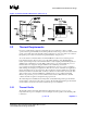
Thermal/Mechanical Reference Design
64-bit Intel
®
Xeon™ Processor MP with 8 MB L3 Cache 19
Thermal/Mechanical Design Guidelines
2.4 Thermal/Mechanical Reference Design
Considerations
2.4.1 Heatsink Solutions
2.4.1.1 Heatsink Design Considerations
To remove the heat from the processor, three basic parameters should be considered:
• The area of the surface on which the heat transfer takes place - Without any
enhancements, this is the surface of the processor package IHS. One method used to improve
thermal performance is by attaching a heatsink to the IHS. A heatsink can increase the
effective heat transfer surface area by conducting heat out of the IHS and into the
surrounding air through fins attached to the heatsink base.
• The conduction path from the heat source to the heatsink fins - Providing a direct
conduction path from the heat source to the heatsink fins and selecting materials with higher
thermal conductivity typically improves heatsink performance. The length, thickness, and
conductivity of the conduction path from the heat source to the fins directly impact the
thermal performance of the heatsink. In particular, the quality of the contact between the
package IHS and the heatsink base has a higher impact on the overall thermal solution
performance as processor cooling requirements become strict. Thermal interface material
(TIM) is used to fill in the gap between the IHS and the bottom surface of the heatsink, and
thereby improves the overall performance of the thermal stackup (IHS-TIM-Heatsink). With
extremely poor heatsink interface flatness or roughness, TIM may not adequately fill the gap.
The TIM thermal performance depends on its thermal conductivity as well as the pressure
load applied to it. Refer to Section 2.4.2 for further information on the TIM between the IHS
and the heatsink base.
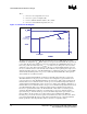
• The heat transfer conditions on the surface on which heat transfer takes place -
Convective heat transfer occurs between the airflow and the surface exposed to the flow. It is
characterized by the local ambient temperature of the air, T
LA
, and the local air velocity over
the surface. The higher the air velocity over the surface, the resulting cooling is more
efficient. The nature of the airflow can also enhance heat transfer via convection. Turbulent
flow can provide improvement over laminar flow. In the case of a heatsink, the surface
exposed to the flow includes the fin faces and the heatsink base.
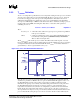
An active heatsink typically incorporates a fan that helps manage the airflow through the heatsink.
Passive heatsink solutions require in-depth knowledge of the airflow in the chassis. Typically,
passive heatsinks see slower air speed. Therefore these heatsinks are typically larger (and heavier)
than active heatsinks due to the increase in fin surface required to meet a required performance. As
the heatsink fin density (the number of fins in a given cross-section) increases, the resistance to the
airflow increases: it is more likely that the air will travel around the heatsink instead of through it,
unless air bypass is carefully managed. Using air-ducting techniques to manage bypass area is an
effective method for maximizing airflow through the heat sink fins.
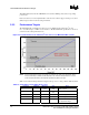
2.4.2 Thermal Interface Material
TIM application between the processor IHS and the heatsink base is generally required to improve
thermal conduction from the IHS to the heatsink. Many thermal interface materials can be pre-
applied to the heatsink base prior to shipment from the heatsink supplier and allow direct heatsink
attach, without the need for a separate TIM dispense or attach process in the final assembly factory.