
64-bit Intel Xeon Processorwith up to 8MB L3 Cache Thermal/Mechanical Design Guidelines
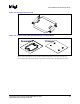


Thermal/Mechanical Reference Design
R
24 64-bit Intel
®
Xeon™ Processor MP with 8 MB L3 Cache
Thermal/Mechanical Design Guidelines
2.4.7.2 Thermal Interface Material (TIM)
A TIM must be applied between the package and the heatsink to ensure thermal conduction. The
cooling solution reference design uses Shin-Etsu* G751 thermal grease.
The recommended grease dispenses weight to ensure full coverage of the processor IHS is given
below. For an alternate TIM, full coverage of the entire processor IHS is recommended.
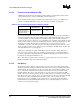
Table 2-4. Recommended Thermal Grease Dispense Weight
Processor
Recommended
Thermal Grease
Dispense Weight
(mg)
64-bit Intel
®
Xeon™
Processor MP with up
to 8 MB L3 Cache
Shin-Etsu* G751 600
It is recommended that you use thermally conductive grease as the TIM requires special handling
and dispense guidelines. The following guidelines apply to Shin-Etsu G751 thermal grease. The use
of a semi-automatic dispensing system is recommended for high volume assembly to ensure an
accurate amount of grease is dispensed on top of the IHS prior to assembly of the heatsink. A typical
dispense system consists of an air pressure and timing controller, a hand held output dispenser, and
an actuation foot switch. Thermal grease in cartridge form is required for dispense system
compatibility. A precision scale with an accuracy of ±5 mg is recommended to measure the correct
dispense weight and set the corresponding air pressure and duration. The IHS surface should be free
of foreign materials prior to grease dispense
Additional recommendations include recalibrating the dispense controller settings after any two
hour pause in grease dispense. The grease should be dispensed just prior to heatsink assembly to
prevent any degradation in material performance. Finally, the thermal grease should be verified to
be within its recommended shelf life before use.
The cooling solution reference solution is designed to apply a compressive load of up to 222 N
[50 lbf] on the TIM to improve the thermal performance.
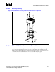
2.4.7.3 Hat Spring
The hat spring, which is attached on the secondary side of the baseboard, is made from 0.80 mm
[0.0315 in.] thick 301 stainless steel half hard. Any future versions of the spring will be made from a
similar material. The hat spring has four embosses (called “hats”) which, when assembled, rest on
the top of the chassis standoffs. The hat spring is located between the chassis standoffs and the
heatsink standoffs. The purpose of the hat spring is to provide compressive preload at the TIM
interface when the baseboard is pushed down upon it. This spring does not function as a clip of any
kind. The two tabs on the spring are used to provide the necessary compressive preload for the TIM
when the whole solution is assembled. The tabs make contact on the secondary side of the
baseboard. In order to avoid damage to the contact locations on the baseboard, the tabs will be
insulated with a 0.127 mm [0.005 in.] thick Kapton* tape (or equivalent). Figure 2-11 shows an
isometric view of the hat spring design.