
64-bit Intel Xeon Processorwith up to 8MB L3 Cache Thermal/Mechanical Design Guidelines

Testing Methods
R
44 64-bit Intel
®
Xeon™ Processor MP with 8 MB L3 Cache
Thermal/Mechanical Design Guidelines
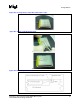
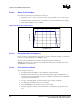
Figure B-12. Removing Excess Adhesive from the IHS
Figure B-13. Filling the Groove with Adhesive
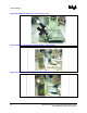
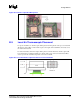
When installing the processor into the socket, make sure that the thermocouple wires exit above the
load plate. Pinching the thermocouple wires between the load plate and the IHS will likely damage
the wires.
Note: When thermocouple wires are damaged, the resulting reading may likely be wrong. For example, if
there are any cuts into the wires insulation where the wires are pinched between the IHS and the
load plate, the thermocouple wires can get in contact at this location. In that case, the temperature
would be really measured will be measured on the edge of the IHS/socket load plate area. This
temperature will likely be much lower than the temperature at the center of the IHS.
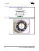
Prior to installing the heatsink, make sure that the thermocouple wires remain below the IHS top
surface, by running a flat blade on top of the IHS for example.