
Intel Xeon Processor 2.80 GHz Thermal/Mechanical Design Guidelines

Dual-Core Intel
®
Xeon
®
Processor 2.80 GHz Thermal/Mechanical Design Guidelines 21
Thermal/Mechanical Reference Design
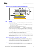
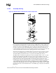
Once the T
CONTROL
value is determined as explained earlier, the thermal diode temperature
reading from the processor can be compared to this T
CONTROL
value. A fan speed control scheme
can be implemented as described in Table 2-3 without compromising the long-term reliability of
the processor.
There are many different ways of implementing fan speed control, including FSC based on
processor ambient temperature, FSC based on processor thermal diode temperature (T
DIODE
) or a
combination of the two. If FSC is based only on the processor ambient temperature, low acoustic
targets can be achieved under low ambient temperature conditions. However, the acoustics cannot
be optimized based on the behavior of the processor temperature. If FSC is based only on the
thermal diode, sustained temperatures above T
CONTROL
, drives fans to maximum RPM. If FSC is
based both on ambient and thermal diode, ambient temperature can be used to scale the fan RPM
controlled by the thermal diode. This would result in an optimal acoustic performance. Regardless
of which scheme is employed, system designers must ensure that the Thermal Profile specification
is met when the processor diode temperature exceeds the T
CONTOL
value for a given processor.
2.3.2 Processor Thermal Characterization Parameter
Relationships
The idea of a “thermal characterization parameter”, Ψ (psi), is a convenient way to characterize the
performance needed for the thermal solution and to compare thermal solutions in identical
conditions (heating source, local ambient conditions). A thermal characterization parameter is
convenient in that it is calculated using total package power, whereas actual thermal resistance,
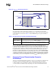
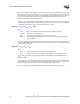
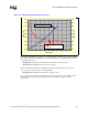
Figure 2-6. T
CONTROL
and Fan Speed Control
Pcontrol_base
TDP
T
CASE
T
CASE
MAX
T
CASE
@
Pcontrol_base
Power
Thermal Profile
T
CASE
@ T
CONTROL
Pcontrol
2
Fan speed control region
1
Pcontrol_base
TDP
T
CASE
T
CASE
MAX
T
CASE
@
Pcontrol_base
Power
Thermal Profile
T
CASE
@ T
CONTROL
Pcontrol
2
Fan speed control region
1
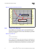
T
CASE
MAX
T
CASE
MAX@T
CONTROL
T
CASE
MAX@
Pcontrol_base
Pcontrol_base
TDP
T
CASE
T
CASE
MAX
T
CASE
@
Pcontrol_base
Power
Thermal Profile
T
CASE
@ T
CONTROL
Pcontrol
2
Fan speed control region
1
Pcontrol_base
TDP
T
CASE
T
CASE
MAX
T
CASE
@
Pcontrol_base
Power
Thermal Profile
T
CASE
@ T
CONTROL
Pcontrol
2
Fan speed control region
1
T
CASE
MAX
T
CASE
MAX@T
CONTROL
T
CASE
MAX@
Pcontrol_base
Table 2-3. Fan Speed Control, T
CONTROL
and T
DIODE
Relationship
Condition FSC Scheme
T
DIODE
≤ T
CONTROL
FSC can adjust fan speed to maintain T
DIODE
= T
CONTROL
(low acoustic region).
T
DIODE
> T
CONTROL
FSC should adjust fan speed to keep T
CASE
at or below the Thermal Profile
specification (increased acoustic region).