
Intel Xeon Processor 2.80 GHz Thermal/Mechanical Design Guidelines

Thermal/Mechanical Reference Design
26 Dual-Core Intel
®
Xeon
®
Processor 2.80 GHz Thermal/Mechanical Design Guidelines
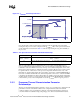
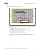
2.4.3 Summary
In summary, considerations in heatsink design include:
• The local ambient temperature T
LA
at the heatsink, airflow (CFM), the power being dissipated
by the processor, and the corresponding maximum T
CASE
. These parameters are usually
combined in a single lump cooling performance parameter, Ψ
CA
(case to air thermal
characterization parameter). More information on the definition and the use of Ψ
CA
is given in
Section 2.4 and Section 2.3.2.
• Heatsink interface (to IHS) surface characteristics, including flatness and roughness.
• The performance of the TIM used between the heatsink and the IHS.
• Surface area of the heatsink.
• Heatsink material and technology.
• Development of airflow entering and within the heatsink area.
• Physical volumetric constraints placed by the system.
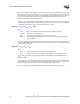
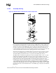
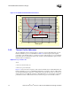
2.4.4 Assembly Overview of the Intel Reference Thermal
Mechanical Design
The reference design heatsinks that meet the Dual-Core Intel Xeon processor 2.80 GHz thermal
performance targets are called the Common Enabling Kit (CEK) heatsinks, and are available in 1U,
2U& 2U+ sizes. Each CEK consists of the following components:
• Heatsink (with captive standoff and screws)
• Thermal Interface Material (TIM-2)
• CEK Spring
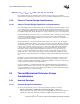
2.4.4.1 Geometric Envelope
The baseboard keepout zones on the primary and secondary sides and height restrictions under the
enabling component region are shown in detail in Appendix A. The overall volumetric keep in
zone encapsulates the processor, socket, and the entire thermal/mechanical enabling solution.