
Intel Xeon Processor 2.80 GHz Thermal/Mechanical Design Guidelines

Dual-Core Intel
®
Xeon
®
Processor 2.80 GHz Thermal/Mechanical Design Guidelines 27
Thermal/Mechanical Reference Design
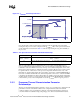
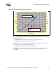
2.4.4.2 Assembly Drawing
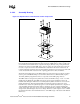
The CEK reference thermal solution is designed to extend air-cooling capability through the use of
larger heatsinks with minimal airflow blockage and bypass. CEK retention solution can allow the
use of much heavier heatsink masses compared to the legacy limits by using a load path directly
attached to the chassis pan. The CEK spring on the secondary side of the baseboard provides the
necessary compressive load for the thermal interface material. The baseboard is intended to be
isolated such that the dynamic loads from the heatsink are transferred to the chassis pan via the stiff
screws and standoffs. This reduces the risk of package pullout and solder-joint failures.
The baseboard mounting holes for the CEK solution are at the same location as the hole locations
used for previous Intel® Xeon® processor thermal solution. However, CEK assembly requires
10.16 mm [0.400 in.] large diameter holes to compensate for the CEK spring embosses.
The CEK solution is designed and optimized for a baseboard thickness range of 1.57 – 2.31 mm.
[0.062-0.093 in]. While the same CEK spring can be used for this board thickness range, the
heatsink standoff height is different for a 1.57 mm [0.062 in] thick board than it is for a 2.31 mm.
[0.093 in] thick board. In the heatsink assembly, the standoff protrusion from the base of the
heatsink needs to be 0.6 mm. [0.024 in] longer for a 2.31 mm [0.093 in] thick board, compared to a
1.57 mm [0.062 in] thick board. If this solution is intended to be used on baseboards that fall
outside of this range, then some aspects of the design, including but not limited to the CEK spring
design and the standoff heights, may need to change. Therefore, system designers need to evaluate
the thermal performance and mechanical behavior of the CEK design on baseboards with different
thicknesses.
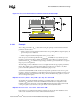
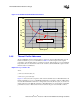
Figure 2-8. Exploded View of CEK Thermal Solution Components