
Intel Xeon Processor 2.80 GHz Thermal/Mechanical Design Guidelines

Thermal/Mechanical Reference Design
36 Dual-Core Intel
®
Xeon
®
Processor 2.80 GHz Thermal/Mechanical Design Guidelines
2.4.8 Boxed Active Thermal Solution for the
Dual-Core Intel Xeon Processor 2.80 GHz
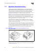
In addition to the 1U and 2U passive CEK heatsinks, Intel is developing an active heatsink
solution. This heatsink solution is primarily designed to be used in a pedestal chassis where
sufficient air inlet space is present and side directional airflow is not an issue. All three heatsinks
will be offered as part of boxed Dual-Core Intel Xeon processor 2.80 GHz products. These
solutions are intended for system integrators who build systems from components available
through distribution channels. The retention solution used for these products is called the Common
Enabling Kit, or CEK. The CEK base is compatible with all three heatsink solutions.
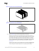
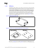
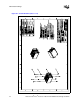
Figure 2-17 provides a representation of the active CEK solution. This design is based on a 4-pin
PWM/T-diode controlled active fan heatsink solution. This new solution is being offered to help
provide better control over pedestal chassis acoustics. This is achieved though accurate
measurement of processor temperature through the processor’s temperature diode (T-diode). Fan
RPM is modulated through the use an ASIC located on the serverboard, that sends out a PWM
control signal to the 4th pin of the connector labeled as Control.
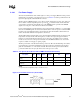
This heatsink solution also requires a constant +12 V supplied to pin 2 and does not support
variable voltage control or 3-pin PWM control. If no PWM signal is detected on the 4
th
pin this
heatsink solution will revert back to thermistor control mode, supporting both the 4-wire PWM and
standard 3-wire ambient air control methods.
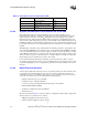
Intel may make changes to specification and product descriptions at any time, without notice. The
active heatsink solution will not exceed a mass of approximately 1150 grams. Note that this is per
processor, so a dual processor system will have up to approximately 2300 grams total mass in the
heatsinks. This large mass will require a minimum chassis stiffness to be met in order to withstand
force during shock and vibration. Please refer to Chassis Strength and Stiffness Measurement and
Improvement Guidelines, for Direct Chassis Attach Solutions for more details on chassis
requirements.
Clearance is required around the heatsink to ensure unimpeded airflow for proper cooling. The
physical baseboard keepout requirements for the active solution are the same as the passive CEK
solution shown in Appendix A.
Figure 2-17. Boxed Active CEK Heatsink Solutions with PWM/T-diode Control
(Representation Only)