
Intel Xeon Processor and Intel E7500/E7501Chipset Compatible Platform Design Guide

Intel
®
Xeon™ Processor and Intel
®
E7500/E7501 Chipset Compatible Platform Design Guide 107
Hub Interface
7.2.2 Hub Interface 2.0 Generation/Distribution of Reference
Voltages
The nominal Hub Interface 2.0 reference voltage is 0.350 V ± 5%. Each Hub Interface 2.0 on the
MCH has a dedicated HIVREF pin to sample this reference voltage. Similarly, the P64H2 has a
dedicated reference voltage pin. In addition to the reference voltage, a reference swing voltage
must be supplied to control buffer voltage swing characteristics. The nominal Hub Interface 2.0
reference swing voltage should be 0.8 V ± 5% for the MCH and P64H2. Each Hub Interface 2.0 on
the MCH has a dedicated HISWNG pin to sample this reference swing voltage. The P64H2 has a
dedicated reference swing voltage pin as well. Both of these reference voltages can be generated
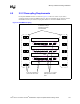
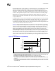
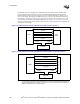
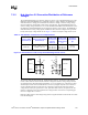
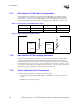
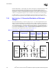
locally with a single voltage divider circuit. Figure 7-5 shows an example voltage divider circuit.
The resistor values R1, R2, R3, R4, R5, and R6 must be rated at ± 1% tolerance. The selected
resistor values must also ensure that the reference voltage and reference swing voltage tolerance
are maintained over the input leakage specification. A 0.1 µF capacitor (C1 in the above circuits)
should be placed close to each resistor divider, and a 0.01 µF bypass capacitor (C2 in the above
circuits) should be placed near each reference voltage pin. If the length of the trace from the
voltage divider to the pin is greater than 1 inch, place more than one 0.01 µF capacitor near the
reference voltage pin. The trace length from the voltage divider circuit to the corresponding pin
must be no longer than 3.5 inches.
Both the voltage reference and voltage swing reference signals should be routed 20 mils to 25 mils
from all other signals.
Table 7-4. Hub Interface 2.0 Reference Circuit Specifications
Reference Voltage
Specification (V)
Reference Swing Voltage
Specification (V)
1.2 V Voltage
DIvider Circuit
Recommended
Resistor
Values (Ω)
1.8 V Voltage
DIvider Circuit
Recommended
Resistor Values
(Ω)
Decoupling
Requirements
(µF)
0.350 ± 5%
For Intel
®
P64H2 = 0.8 ± 5%
For MCH = 0.8 ± 5%
R1 = 392 ± 1%
R2 = 499 ± 1%
R3 = 453 ± 1%
R4 = 261 ± 1%
R5 = 332 ± 1%
R6 = 750 ± 1%
C1 = 0.1
C2 = 0.01
Figure 7-5. Hub Interface 2.0 with Locally Generated Voltage Divider Circuit
MCH
HISWNG_x
HIVREF_x
Intel
®
P64H2
0.35 V
0.35 V
0.8 V
0.8 V
HI_VSWING
HI_VREF
R4
R5
R6
R3
R2
R1
C2C1
C1
C1
C1
C2
C2
C2
1.2 V
1.8 V