
Intel Xeon Processor and Intel E7500/E7501Chipset Compatible Platform Design Guide


Intel
®
Xeon™ Processor and Intel
®
E7500/E7501 Chipset Compatible Platform Design Guide 123
Intel
®
82870P2 (P64H2)
8.2 Hot-Plug Implementation
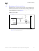
The P64H2 contains two integrated Hot-Plug controllers (one per PCI/PCI-X interface) that
operate independently. These integrated controllers can be individually disabled or configured to
operate in one of the three defined modes of operation: single-slot parallel mode, dual-slot parallel
mode, and serial mode. This section describes each of these three modes of operation, as well as
switch and button implementation and the Hot-Plug Standard Usage Model.
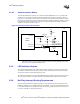
8.2.1 Standard Usage Model
To define a programming model for the Hot-Plug controllers (HPC), it is necessary to make some
assumptions about the interface between a user and a Hot-Plug system that must be incorporated
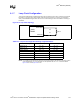
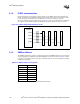
into the hardware solution. The programming model includes two LED indicators, one optional
push button, and a sensor on the manually-operated retention latch (MRL) for each supported slot.
See Section 8.2.2 for MRL and attention button implementation. Section 8.2.3 describes the LED
indicators. For more information on the Hot-Plug Standard Usage Model, see the PCI Standard
Hot-Plug Controller and Subsystem Specification, Revision 1.0.
Caution: Users must always notify the operating system via a software user interface or Attention Button
(if present) before opening an MRL. This allows the operating system to isolate the slot from the
PCI bus and unload the device driver gracefully. The unexpected opening of an MRL leads to
unpredictable results, including data corruption, abnormal termination of the operating system, or
damage to card or platform hardware.
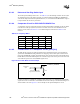
8.2.1.1 Hot-Removals
1. User selects a slot holding an enabled add-in card and requests that slot be disabled.
a. User interacts with a software user interface to request that slot be disabled.
b. User confirms request. System software validates request and initiates slot power down
sequence. Power Indicator LED blinks.
– OR –
a. User presses momentary Attention Button at that slot.
b. Software interprets change on HxPRSNT# pin as a push button event. (Software ignores
second interrupt on HxPRSNT# caused by button release.) Power Indicator LED blinks.
c. User is permitted to cancel request within 5 seconds by pressing Attention Button again.
d. System software validates request and initiates slot power down sequence.
2. System software waits for card activity on the PCI bus to end.
3. Hot-Plug controller asserts RST#, bus signals and clock lines are disconnected from the slot,
and power is removed.
4. Power Indicator LED is turned off. User may open MRL, disconnect cables, and remove card.