
Intel Xeon Processor and Intel E7500/E7501Chipset Compatible Platform Design Guide


Intel
®
Xeon™ Processor and Intel
®
E7500/E7501 Chipset Compatible Platform Design Guide 147
I/O Controller Hub 3 (Intel
®
ICH3-S)
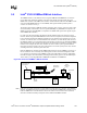
9.4 USB
The ICH3-S contains three UHCI Host controllers. Each UHCI controller includes a root hub with
two separate USB ports, for a total of six USB ports. This section provides guidelines for routing
USB.
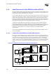
9.4.1 General Routing and Placement
Use the following general routing and placement guidelines when laying out a new design. These
guidelines help minimize signal quality and EMI problems. USB validation efforts have focused on
a ground referenced design.
1. Place the ICH3-S and major components on the un-routed board first. With minimum trace
lengths, route high-speed clock, periodic signals, and USB differential pairs first. Maintain
maximum possible distance between high-speed clocks/periodic signals to USB differential
pairs and any connector leaving the PCB (i.e., I/O connectors, control and signal headers, or
power connectors).
2. USB signals should be ground referenced (on layers 3 and 6).
3. Route USB signals using a minimum of vias and corners. This reduces reflections and
impedance changes.
4. When it becomes necessary to turn 90 degrees, use two 45-degree turns or an arc instead of a
single 90 degree turn. This reduces reflections on the signal by minimizing impedance
discontinuities.
5. Do not route USB traces under crystals, oscillators, clock synthesizers, magnetic devices or
ICs that use and/or duplicate clocks.
6. Stubs on USB signals should be avoided because stubs have an effect on signal quality. If stubs
are necessary, none should be greater than 200 mils.
7. Route all traces over continuous ground planes with no interruptions. Avoid crossing over anti-
etch if possible; this increases inductance and radiation levels by forcing a greater loop area.
Likewise, avoid changing layers with high-speed traces.
8. Keep USB signals clear of the core logic set. High current transients are produced during
internal state transitions, and can be very difficult to filter out.
9. Keep traces at least 50 mils away from the edge of the plane. This helps prevent the coupling
of the signal onto adjacent wires, and helps prevent free radiation of the signal from the edge
of the PCB.