
Intel Xeon Processor and Intel E7500/E7501Chipset Compatible Platform Design Guide

I/O Controller Hub 3 (Intel
®
ICH3-S)
156 Intel
®
Xeon™ Processor and Intel
®
E7500/E7501 Chipset Compatible Platform Design Guide
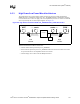
9.6.4 RTC Layout Considerations
Since the RTC circuit is very sensitive and requires high accurate oscillation, reasonable care must
be taken during layout and routing of the RTC circuit. Some recommendations are:
• Reduce trace capacitance by minimizing the RTC trace length. ICH3-S requires a trace length
less than 1 inch on each branch (from crystal's terminal to RTCXn ball). Route the RTC circuit
short to simplify the trace length measurement and increase accuracy when calculating trace
capacitances. Trace capacitance depends on the trace width and dielectric constant of the
board’s material. On FR-4, a 5-mil trace has approximately 2 pF per inch.
• Reduce trace signal coupling by avoiding routing of adjacent PCI signals close to RTCX1,
RTCX2, and VBIAS.
• A ground guard plane is highly recommended.
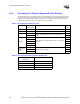
9.6.5 RTC External Battery Connection
The RTC requires an external battery connection to maintain its functionality and its RAM while
the ICH3-S is not powered by the system.
Example batteries are: Duracell 2032, 2025, or 2016 (or equivalent), which can give many years of
operation.
Batteries are rated by storage capacity. The battery life can be calculated by dividing the capacity
by the average current required. For example, if the battery storage capacity is 170 mAh
(assumed usable), and the average current required is 3 µA, the battery life will be at least:
170,000 µAh / 3 µA = 56,666 h = 6.4 years
The voltage of the battery can affect the RTC accuracy. In general, when the battery voltage
decays, the RTC accuracy also decreases. The battery voltage of the RTC must be greater than 2 V
at all times to ensure the accuracy of the RTC clock.
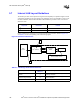
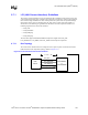
Connect the battery to the ICH3-S via an isolation diode circuit. The diode circuit allows the
ICH3-S RTC-well to be powered by the battery when the system power is not available, and by the
system power when it is available. To do this, the diodes are set to be reverse biased when the
system power is not available. Figure 9-11 is an example of a diode circuit. As noted, a standby
power supply should be used in a server system to provide continuous power to the RTC when
available to significantly increase the RTC battery life.
9.6.6 VBIAS DC Voltage and Noise Measurements
VBIAS is a DC voltage level that is necessary for biasing the RTC oscillator circuit. This DC
voltage level is filtered out from the RTC oscillation signal by the RC Network of R2 and C3
(see Figure 9-11); therefore, it is a self-adjusted voltage. Board designers should not manually bias
the voltage level on VBIAS. Checking VBIAS level is used for testing purposes only to determine
the right bias condition of the RTC circuit.
VBIAS should be at least 200 mV DC. The RC network of R2 and C3 filters out most of the AC
signals that exist on this ball. However, the noise on this ball should be kept to a minimum to
guarantee the stability of the RTC oscillation.