
Intel Xeon Processor and Intel E7500/E7501Chipset Compatible Platform Design Guide

I/O Controller Hub 3 (Intel
®
ICH3-S)
160 Intel
®
Xeon™ Processor and Intel
®
E7500/E7501 Chipset Compatible Platform Design Guide
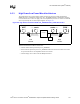
9.7.1.2 LCI Routing Parameters
Route the LCI signals carefully on the motherboard to meet the timing and signal quality
requirements of this interface specification. The board designer should simulate the board routing
to verify that the specifications are met for flight times and skews due to trace mismatch and
crosstalk.
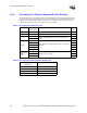
Table 9-4. LCI Routing Parameter Summary
Parameter Requirements
Trace Impedance (Z
0
) 60 Ω ± 15% due to signal integrity requirements.
Trace Spacing Minimum of 100 mils from non-LCI signals
Termination 33
Ω series resistor can be installed at the driver side of the interface.
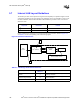
Length Tuning
On the motherboard, the length of each data trace should be either equal in length
to the LAN_CLK trace, or up to 0.5 inch shorter than the LAN_CLK trace.
LAN_CLK should always be the longest motherboard trace in each group.
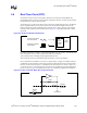
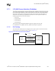
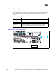
Figure 9-14. LAN_CLK Routing Example
LAN_CLK
LAN_RXD0