
Intel Xeon Processor and Intel E7500/E7501Chipset Compatible Platform Design Guide

Intel
®
Xeon™ Processor and Intel
®
E7500/E7501 Chipset Compatible Platform Design Guide 161
I/O Controller Hub 3 (Intel
®
ICH3-S)
9.7.2 General LAN Routing Guidelines and Considerations
9.7.2.1 General Trace Routing Considerations
Trace routing considerations are important to minimize the effects of crosstalk and propagation
delays on sections of the board where high-speed signals exist. Signal traces should be kept as short
as possible to decrease interference from other signals, including those propagated through power
and ground planes. Observe the following suggestions to help optimize board performance:
• Maintain constant symmetry and spacing between the traces within a differential pair.
• Keep the signal trace lengths of a differential pair equal to each other.
• Keep the total length of each differential pair under 4 inches. (Many customer designs with
differential traces longer than 5 inches have had one or more of the following issues: IEEE phy
conformance failures, excessive EMI, and/or degraded receive BER [Bit Error Rate].)
• Do not route the transmit differential traces closer than 100 mils to the receive differential
traces.
• Do not route any other signal traces parallel to the differential traces, or closer than 100 mils to
the differential traces (300 mils is recommended).
• Keep maximum separation between differential pairs to 7 mils.
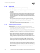
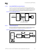
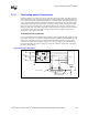
• For high-speed signals, the number of corners and vias should be kept to a minimum. If a
90 degree bend is required, it is recommended to use two 45-degree bends instead. Refer to
Figure 9-15.
• Traces should be routed away from board edges by a distance greater than the trace height
above the ground plane. This allows the field around the trace to couple more easily to the
ground plane rather than to adjacent wires or boards.
• Do not route traces and vias under crystals or oscillators. This will prevent coupling to or from
the clock. And as a general rule, place traces from clocks and drives at a minimum distance
from apertures by a distance that is greater than the largest aperture dimension.
Figure 9-15. Routing a 90-Degree Bend
45°