
Intel Xeon Processor and Intel E7500/E7501Chipset Compatible Platform Design Guide

I/O Controller Hub 3 (Intel
®
ICH3-S)
162 Intel
®
Xeon™ Processor and Intel
®
E7500/E7501 Chipset Compatible Platform Design Guide
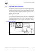
9.7.2.2 Trace Geometry and Length
The key factors in controlling trace EMI radiation are the trace length, and the ratio of trace-width
to trace-height above the ground plane. To minimize trace inductance, high-speed signals and
signal layers that are close to a ground or power plane should be as short and wide as practical.
Ideally, this trace width to height above the ground plane ratio is between 1:1 and 3:1. To maintain
trace impedance, the width of the trace should be modified when changing from one board layer to
another if the two layers are not equidistant from the power or ground plane. Differential trace
impedances should be controlled to be ~100
Ω. It is necessary to compensate for trace-to-trace edge
coupling, which can lower the differential impedance by up to 10
Ω, when the traces within a pair
are closer than 30 mils (edge-to-edge).
Traces between decoupling and I/O filter capacitors should be as short and wide as practical. Long
and thin traces are more inductive and would reduce the intended effect of decoupling capacitors.
Also, for similar reasons, traces to I/O signals and signal terminations should be as short as
possible. Vias to the decoupling capacitors should be sufficiently large in diameter to decrease
series inductance. Additionally, the PLC should not be closer than 1 inch to the connector/magnetic
edge of the board.
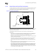
9.7.2.3 Signal Isolation
Follow these rules for signal isolation:
• Separate and group signals by function on separate layers if possible. Maintain a gap of
100 mils between all differential pairs (Ethernet) and other nets, but group associated
differential pairs together. Over the length of the trace run, each differential pair should be at
least 0.3 inch away from any parallel signal traces.
• Physically group together all components associated with one clock trace to reduce trace
length and radiation.
• Isolate I/O signals from high speed signals to minimize crosstalk, which can increase EMI
emission and susceptibility to EMI from other signals.
• Avoid routing high-speed LAN or Phoneline traces near other high-frequency signals
associated with a video controller, cache controller, processor, or other similar devices.
9.7.2.4 Power and Ground Connections
Follow these rules for power and ground connections:
• All VCC balls should be connected to the same power supply.
• All VSS balls should be connected to the same ground plane.
• Four to six decoupling capacitors, including two 4.7 µF capacitors, are recommended.
• Place decoupling as close as possible to power balls.