
Intel Xeon Processor and Intel E7500/E7501Chipset Compatible Platform Design Guide


Intel
®
Xeon™ Processor and Intel
®
E7500/E7501 Chipset Compatible Platform Design Guide 169
I/O Controller Hub 3 (Intel
®
ICH3-S)
9.7.5 Terminating Unused Connections
In Ethernet designs, it is common practice to terminate unused connections on the RJ45 connector
and the magnetics module to ground. Depending on overall shielding and grounding design, this
may be done to the chassis ground, signal ground, or a termination plane. Care must be taken when
using various grounding methods to insure that emission requirements are met. The method most
often implemented is called the “Bob Smith” Termination. In this method, a floating termination
plane is cut out of a power plane layer. This floating plane acts as a plate of a capacitor with an
adjacent ground plane, and couples capacitively to the ground plane creating the required 1500 pF
of capacitance. The signals can be routed through 75
Ω resistors to the plane. Stray energy on
unused pins is then carried to the plane.
Termination Plane Capacitance
It is recommended that the termination plane capacitance equal a minimum value of 1500 pF. This
helps reduce the amount of crosstalk on the differential pairs (TDP/TDN and RDP/RDN) from the
unused pairs of the RJ45. Pads may be placed for an additional capacitance to chassis ground,
which may be required if the termplane capacitance is not large enough to pass EFT (Electrical
Fast Transient) testing. If a discrete capacitor is used to meet the EFT requirements, it should be
rated for at least 1000 Vac.
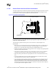
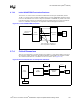
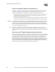
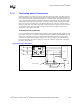
Figure 9-19. Termination Plane
N/C
RJ45
Magnetics module
RDP
RDN
TDP
TDN
Termination plane
Additional capacitance that may be
required for EFT testing