
Intel Xeon Processor and Intel E7500/E7501Chipset Compatible Platform Design Guide

Intel
®
Xeon™ Processor and Intel
®
E7500/E7501 Chipset Compatible Platform Design Guide 71
System Bus Routing Guidelines
5.3.5 TESTHI[6:0] Routing Guidelines
All TESTHI[6:0] pins must be connected to VCC_CPU via pull-up resistors with a pull-up value
within 20% of the signal impedance (50 Ω ± 20%). TESTHI[3:0] may all be tied together and
pulled up to VCC_CPU with a single, 50 Ω ± 20% resistor if desired. TESTHI[6:5] may also be
tied together and pulled up to VCC_CPU with a single 50 Ω ± 20% resistor. However, boundary
scan testing will not be functional if any TESTHI pins are pulled up together. TESTHI4 must
always be pulled up independently from the other TESTHI pins regardless of the usage of
boundary scan.
5.3.6 Asynchronous GTL+ Signals Driven by the Chipset
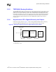
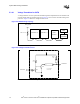
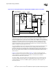
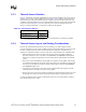
Follow the topology shown in Figure 5-7 when routing A20M#, IGNNE#, INIT#, LINT[1:0],
CPUSLP#, SMI# and STPCLK#. Do not route a stub when routing to the processors.
NOTES:
1. Trace Z
0
= 50 Ω
2. Trace spacing = 10 mil
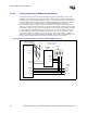
Figure 5-7. Topology for Asynchronous GTL+ Signals Driven by the Chipset
Intel
®
ICH3-S
Processor 0 Processor 1
0.1" – 3.0"
0.1" – 9.0" 0.1" – 9.0"
VCC_CPU
200 Ω ± 5%