
Intel Xeon Processor and Intel E7500/E7501Chipset Compatible Platform Design Guide

System Bus Routing Guidelines
74 Intel
®
Xeon™ Processor and Intel
®
E7500/E7501 Chipset Compatible Platform Design Guide
5.5 SMBus Implementation
Intel Xeon processors with 512-KB L2 cache contain SMBus devices (i.e., PIROM, Scratch
EEPROMs, and thermal sensor). Intel Xeon processors with 533 MHz system bus do not contain
these SMBus devices. The following sections provide guidelines for designing a system to operate
with both processors with respect to these SMBus features.
5.5.1 Intel
®
Xeon™ Processor with 512-KB L2 Cache SMBus
Signals
The Intel Xeon processor with 512-KB L2 cache (INT-mPGA package) contains SMBus devices
(i.e., PIROM, Scratch EEPROMs, and thermal sensor). The SMBus signals provide access to the
thermal sensor and memory device on the processor. The signaling protocol used adheres to the
specification of the System Management Bus. Refer to Intel
®
Xeon™ Processor Datasheet for
details on the Intel Xeon processor implementation and addressing scheme.
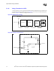
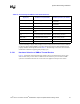
Connect the SM_ALERT#, SM_CLK, and SM_DAT signals to the SMBus controller in adherence
to the System Management Bus (SMBus) Specification, Version 1.1. These signals can be connected
to other processors on the same SMBus.
The SM_EP_A[2:0] signals set the SMBus address for the memory device on the processor. These
signals must be set at power up with a unique address per bus. They have an internal 10 kΩ ± 5%
pull-down. To pull the SM_EP_A[2:0] signals to a logic high level, connect each signal to a
100 Ω ± 5% resistor tied to SM_VCC. Refer to the section on SMBus Device Addressing in the
processor datasheet for addressing details.
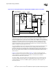
The SM_TS_A[1:0] signals set the SMBus address for the thermal device on the processor. These
signals must be set at power up with a unique address per bus. The SM_TS_A[1:0] can be set to
logic high, logic low, or a high impedance state giving nine possible combinations of addresses.
Refer to the section on SMBus Device Addressing in the processor datasheet for addressing details.
The SM_TS_A[1:0] signals do not have an internal pull-down and thus must be pulled to VSS or
SM_VCC with a 1 kΩ ± 5% or smaller resistor. Leaving the pins floating achieves a high-Z state.
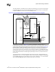
The SM_WP signal is a write protect signal for the memory device. Pulling this signal to SM_VCC
with a 100 Ω ± 5% resistor enables write protection. SM_WP has an internal 10 kΩ pull-down.
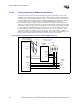
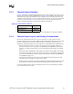
5.5.2 Thermal Diode and SMBus Interface
Intel Xeon processors with 533 MHz system bus provide voltage readings directly from the
processor core’s thermal diode via the THERMDA1 (pin Y27) and THERMDC1 (pin Y28) signals.
Note that these signals are not used on the Intel Xeon processors with 512-KB L2 cache since
thermal data is obtained via the SMBus from the thermal sensor. Table 5-9 summarizes the
functionality of the thermal diode and applicable SMBus pins on both processor package types.