
Intel Xeon Processor and Intel E7500/E7501Chipset Compatible Platform Design Guide

Intel
®
Xeon™ Processor and Intel
®
E7500/E7501 Chipset Compatible Platform Design Guide 77
System Bus Routing Guidelines
The SCLK, SDATA, and ALRT# must not exhibit increased leakage current when the VDD supply
is grounded. If this is the case, then the motherboard pull-up resistance needs to be evaluated for
acceptable VIHMIN levels due to the increased leakage current.
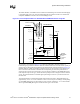
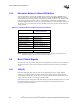
The reference circuit shown in Figure 5-11 assumes the Field Effect Transistor (FET) is a
P-channel logic type with low source-to-drain on-resistance and source-to-drain current capacity to
supply power to the thermal sensor. Based on the thermal sensor components listed in Figure 5-10,
the FET should be capable of handling a minimum of 180 µA source-drain current and have less
than 1 Ω source-drain resistance. The FET also needs specific gate electrical specifications to
support the two logic levels presented by a processor-driven grounded or open SMB_PRT signal
(state depends on processor type), and the associated pull-up resistor\voltage used in the reference
circuit. The FET should have a maximum gate input leakage current of 1 µA when the FET is in
the OFF state.
The FET should have a minimum\maximum VGS-Thresh (Gate-Source Threshold Voltage) of
approximately -0.4 V\-1.0 V. The “minimum” value of -0.4 V will prevent leakage current pulling
an open SMB_PRT signal to an electrically low state. And the “maximum” -1.0 V value will still
allow a grounded SMB_PRT signal to switch the FET's gate to an ON state.
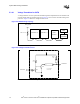
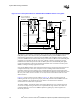
Figure 5-11. Circuit Implementation for Hardware-Based SMBus Selection Using FET
Y28
Y27
3
ADD1
ADD0
VDD
SM_VCC
Thermal Sensor
Processor
15
14
12
11
STBY#
SCLK
SDATA
ALRT#
SM_VCC
AC28
AC29
AD28
SM_CLK
SM_DAT
SM_ALERT#
Onboard
SMBus Signals
THERMDA
THERMDC
SM_CLK
SM_DAT
SM_ALERT#
AA28
Y29
SM_TS1_A0
SM_TS1_A1
SMB_PRT
6
10
2
Use any Combination of
resistors for addresses.
4
7, 8
1, 5, 9, 11, 16
D+
D-
GND
NC
AE4
SM_VCC
100 kΩ
1 kΩ