
Intel Xeon Processor and Intel E7500/E7501Chipset Compatible Platform Design Guide

Intel
®
Xeon™ Processor and Intel
®
E7500/E7501 Chipset Compatible Platform Design Guide 81
System Bus Routing Guidelines
5.6.2 SKTOCC# Signal Routing Guidelines
The SKTOCC# signal is an output from the processor used as an indication of whether a processor
is installed or not. It is asserted low when a processor is installed in the socket, and floats when no
processor is present. If this signal is used on the board, the designer can use a pull-up to prevent
floating. SKTOCC# can be used to disable the VRM or VRD output for unpopulated processor
sockets or the power supply output when no processors are installed and other features.
5.6.3 BSEL[1:0] Implementation
The processor provides two output signals named BSEL[1:0] that the motherboard uses to identify
the system bus frequency supported by the installed processor. The BSEL[1:0] output values are
shown in Table 5-12. The recommended pull-up value for BSEL with the comparator in
Section 11.2.6 is a 1 kΩ, though the designer should ensure that the proper VIH and VIL is
maintained for the receiver. These outputs may be used by motherboard logic to:
• Automatically select the proper system bus clock frequency driven by the CK408B.
• Verify both processors support the same system bus frequency. If processor system bus
frequencies do not match, then disable the voltage regulator output which supplies power to
the processors.
BSEL[1:0] have a power sequencing requirement discussed in Section 11.2.6.
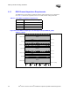
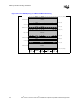
5.6.4 Sample Implementation Circuit
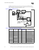
Figure 5-13 shows an example BSEL[1:0] motherboard implementation that is incorporated into
the E7501 MCH Customer Reference Board. This circuit performs those functions mentioned
previously and leverages the existing VID comparator logic used on the E7500 Chipset Customer
Reference Board. The major addition is that BSEL[1:0] outputs from both processor sockets are
routed to the P6/P5 and Q6/Q5 inputs of the VID comparator. The comparator will check that all
VID[4:0] and BSEL[1:0] signal values match on both processors. The SKTOCC# signal is also
utilized, to determine when Socket 1 is not populated (i.e., only one processor is present).
The first condition of this circuit that enables the voltage regulator is when the VIDs and BSELs
match. If both processors are installed and running with the same VID and BSEL values, a low
goes to the input of the NAND from the comparator, enabling the voltage regulator.
The second condition of this circuit which enables the voltage regulator is when Socket 1 is not
populated. If a processor is only present in Socket 0, an erroneous mismatch signal is ignored, and
the low asserted from the inverter ensures the NAND outputs a high, enabling the voltage
regulator.
The condition that disables the voltage regulator is when both inputs to the NAND are high. In this
case, there is both a mismatch (comparator outputs a high) and a populated Socket 1
(the SKT_OCC# inverter outputs a high). In this instance, the NAND outputs a low, disabling the
voltage regulator. If both processors are present, the VIDs and BSELs do not match. If Socket 1 is
populated and Socket 0 is not, a mismatch occurs, disabling the voltage regulator.
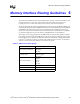
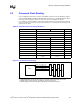
Table 5-12. BSEL[1:0] Output
System Bus Speed BSEL1 BSEL0
400 MHz L L
533 MHz L H