
Intel Xeon Processor with 800 MHz System Bus Thermal/Mechanical Design Guide

18 Intel® Xeon™ Processor with 800 MHz System Bus Thermal/Mechanical Design Guidelines
Thermal/Mechanical Reference Design
2.2.3 Dual Thermal Profile Concept for the Intel® Xeon™
Processor with 800 MHz System Bus
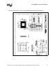
The Intel Xeon Processor with 800 MHz System Bus is designed to go into various form factors,
including the volumetrically constrained 1U and custom blade form factors. Due to certain
limitations of such form factors (i.e. airflow, thermal solution height), it is very challenging to meet
the thermal requirements of the processor. To mitigate these form factor constraints, Intel has
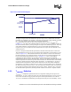
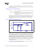
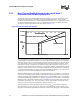
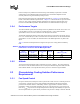
developed a dual Thermal Profile specification, shown in Figure 2-4.
The Thermal Profile A is based on Intel’s 2U+ air cooling solution. Designing to Thermal Profile
A ensures that no measurable performance loss due to Thermal Control Circuit (TCC) activation is
observed in the processor. It is expected that TCC would only be activated for very brief periods of
time when running a worst-case real world application in a worst-case thermal condition. These
brief instances of TCC activation are not expected to impact the performance of the processor. A
worst case real world application is defined as a commercially available, useful application which
dissipates a power equal to, or above, the TDP for a thermally relevant timeframe. One example of
a worst-case thermal condition is when a processor local ambient temperature is at or above 43 °C
for Intel Xeon Processor with 800 MHz System Bus Thermal Profile A.
Thermal Profile B supports volumetrically constrained platforms (i.e. 1U, blades, etc), and is based
on Intel’s 1U air cooling solution. Because of the reduced capability represented by such thermal
solutions, designing to Thermal Profile B results in an increased probability of TCC activation and
an associated measurable performance loss. Refer to Appendix F for more details on the Thermal
Monitor features. Measurable performance loss is defined to be any degradation in the processor’s
performance greater than 1.5%. The 1.5% number is chosen as the baseline since the run-to-run
variation in a given performance benchmark is typically between 1 - 2%.
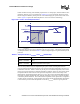
Although designing to Thermal Profile B results in increased T
CASE
temperatures compared to
Thermal Profile A at a given power level, both of these Themal Profiles ensure that Intel’s long-
term processor reliability requirements are satisfied. In other words, designing to Thermal Profile
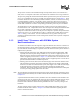
Figure 2-4. Dual Thermal Profile Diagram
Pcontrol_base_A
TDP
T
CASE
T
CASE
MAX B
T
CASE
@
Pcontrol_base
Thermal Profile B
T
CASE
MAX A
Thermal Profile A
Pcontrol_base_B
Pcontrol_base_A
TDP
T
CASE
T
CASE
MAX B
T
CASE
@
Pcontrol_base
Thermal Profile B
T
CASE
MAX A
Thermal Profile A
Pcontrol_base_B