
Intel Xeon Processor with 800 MHz System Bus Thermal/Mechanical Design Guide

30 Intel® Xeon™ Processor with 800 MHz System Bus Thermal/Mechanical Design Guidelines
Thermal/Mechanical Reference Design
2.4.7 Components Overview
2.4.7.1 Heatsink with Captive Screws and Standoffs
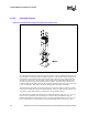
The CEK reference heatsink uses snapped-fin technology for its design. It consists of a copper
base and copper fins with Shin-Etsu* G751 thermal grease as the TIM. The mounting screws and
standoffs are also made captive to the heatsink base for ease of handling and assembly as shown in
Figure 2-10 and Figure 2-11 for the 2U+ and 1U heatsinks, respectively.
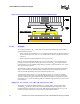
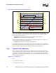
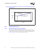
Figure 2-9. 1U CEK Thermal Adherence to Intel® Xeon™ Processor with 800 MHz System Bus
Thermal Profile B
0
10
20
30
40
50
60
70
80
90
0 102030405060708090100110
Power [W]
Tcase [°C]
Thermal Profile B
y = 0.35 * x + 44
1U CEK Reference Solution
y = 0.384 * x + 40
T
CASE_MAX
@
Pcontrol_base
P
CONTROL_BASE_A
T
CASE_MAX_B
@
TDP
TDP
0
10
20
30
40
50
60
70
80
90
0 102030405060708090100110
Power [W]
Tcase [°C]
Thermal Profile B
y = 0.35 * x + 44
1U CEK Reference Solution
y = 0.384 * x + 40
T
CASE_MAX
@
Pcontrol_base
P
CONTROL_BASE_A
T
CASE_MAX_B
@
TDP
TDP