
Intel Xeon Processor with 800 MHz System Bus Thermal/Mechanical Design Guide

Intel® Xeon™ Processor with 800 MHz System Bus Thermal/Mechanical Design Guidelines 31
Thermal/Mechanical Reference Design
Note: Refer to Appendix A for more detailed mechanical drawings of the heatsink.
Note: Refer to Appendix A for more detailed mechanical drawings of the heatsink.
The function of the standoffs is to provide a bridge between the chassis and the heatsink for
attaching and load carrying. When assembled, the heatsink is rigid against the top of the standoff,
and the standoff is rigid to a chassis standoff with the hat spring firmly sandwiched between the
two. In dynamic loading situations the standoff carries much of the heatsink load, especially in
lateral conditions, when compared to the amount of load transmitted to the processor package. As
such, it is comprised of steel. The distance from the bottom of the heatsink to the bottom of the
standoff is 1.02 cm [0.402 in.].
The function of the screw is to provide a rigid attach method to sandwich the entire CEK assembly
together, activating the hat spring under the baseboard, and thus providing the TIM preload. A
screw is an inexpensive, low profile solution that does not negatively impact the thermal
performance of the heatsink due to air blockage. Any fastener (i.e. head configuration) can be used
as long as it is of steel construction; the head does not interfere with the heatsink fins, and is of the
correct length of 1.27 cm [0.50 in.].
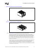
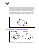
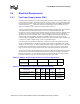
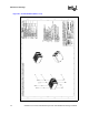
Figure 2-10. Isometric View of the 2U+ CEK Heatsink
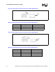
Figure 2-11. Isometric View of the 1U CEK Heatsink