
Intel Xeon Processor with 800 MHz System Bus Thermal/Mechanical Design Guide

60 Intel® Xeon™ Processor with 800 MHz System Bus Thermal/Mechanical Design Guidelines
Test Setup Methodology
B.1.2 Thermocouple Attachment, Air Temperature and Velocity
Measurements
Hysol Epoxy-Patch #309* or equivalent may be used for bonding thermocouples to the heat
sources. A good thermal bond between the thermocouple and the device being measured is
essential. However, excessive bonding material can affect the measurement for small devices
particularly if the bonding material has a significantly different thermal conductivity compared to
the device being tested. The standard thermocouple mounting location will be at the top, geometric
center of the component unless otherwise noted.
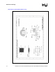
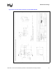
Velocity probes will be placed using hot glue with the face of the probe set perpendicular to the
primary flow direction. To support these probes in the air stream, toothpicks or paper clips may be
attached to the probes for stability. It is important to note that velocity readings represent a single
point in space and should not be used to calculate the volumetric airflow entering a given region.
To calculate an approximate volumetric airflow, several measurements should be averaged to
capture the velocity gradient in that region. Nevertheless, single velocity measurements are useful
in making relative qualitative comparisons between regions. If the probe is close to the flow source
(i.e. fans, blowers, etc.), a wide range of readings may be measured and result in the need for
multiple velocity measurements.
Note: Special attention should be made when mounting air velocity probes. The probe readings are
extremely sensitive to alignment with the flow and any misalignment will compromise the
measurement result.
B.1.2.1 Processor Thermocouple Placement
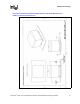
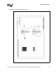
Processor cooling performance is determined by measuring the processor case temperature using a
30-36 AWG thermocouple. For processor case temperature measurements, the 0° attachment
method is recommended for mounting a thermocouple (see Figure B-20). This method consists of
milling a slot into the top of the processor IHS. For a 36 AWG thermocouple, the recommended
depth and width of the channel are 0.4 mm and 0.8 mm, respectively. If larger gauge thermocouple
wires are used, the milled slot should only be large enough so that the thermocouple bead and wire
do not protrude above the plane of the IHS. The thermocouple is then placed in the milled channel
with the tip bonded to the surface to be measured. The milled channel and thermocouple
placement are carefully examined to ensure that the IHS surface is not compromised by any burrs
or epoxy. To ensure direct contact of the thermocouple bead with the IHS channel surface, the
engineer should test for continuity between the thermocouple wire and the heat spreader.