
ITP700 Debug Port Design Guide

R
18 ITP700 Debug Port Design Guide
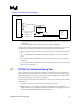
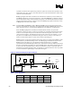
The advantages of this ITP700 Flex are a significantly reduced footprint and keepout volume.
Please refer to the ITP700Flex specifications chapter for the mechanical specifications.
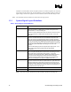
1.4.1 Signal Descriptions
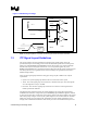
The pinout of the debug port connector at the end of the ITP700 Flex is identical to that of the
standard debug port connector. See Figure 4 for details.
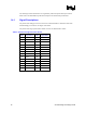
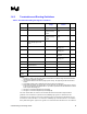
The pinout of the target system surface mount connector for ITP700 Flex is below.
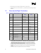
Table 5. ITP700 Flex Edge Connector Pinout
Pad # Signal Name Pad # Signal Name
1 TDI 2 TMS
3 TRST# 4 NC1
5 TCK 6 NC2
7 TDO 8 BCLKn
9 BCLKp 10 GND
11 FBO 12 RESET#
13 BPM5# 14 GND
15 BPM4# 16 GND
17 BPM3# 18 GND
19 BPM2# 20 GND
21 BPM1# 22 GND
23 BPM0# 24 DBA#
25 DBR# 26 VTAP
27 VTT 28 VTT