
ITP700 Debug Port Design Guide

R
ITP700 Debug Port Design Guide 21
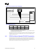
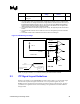
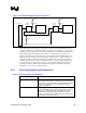
Figure 4. ITP700 Flex Required Layout of BPM[5:0]#
D1
D
ebug Port
Connector
BPM[0]# Signal
BPM[1]# Signal
BPM[2]# Signal
BPM[3]# Signal
BPM[4]# Signal
BPM[5]# Signal
Rt
Rt Rt
Rt
Rt
Rt
Vcc
BPM#
0 1 2 3 4 5
uProcessor
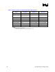
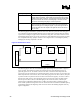
Table 8. BPM[5:0]# Definitions
Parameter Min Nominal Max Notes
D1 1 ns 1,2
Rt 3
NOTES:
1. This signal must be length matched to RESET# to within 50 ps.
2. D1 is defined as the total length from the processor driver to the corresponding BPM at the connector.
3. Characteristic Impedance of Transmission Line
Vtap should be connected to the same supply as provides the voltage of the JTAG pull-up resistors
on the target system. This connection is lightly loaded (<50 mA). Check your platform, as this
voltage may be the same as Vtt.
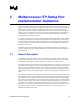
1.4.3 ITP700 Flex Deltas to Standard ITP AC/DC Characteristics
The following data represents the changes to the AC/DC specifications from the ITP700 DPA or
the ITP700 LVDPA to be used with the ITP700 Flex. Note that this table only represents the
changes to the base tables. Please reference the AC/DC Specifications for the ITP700 DPA or the
ITP700 LVDPA in the Specifications chapters for debug port style of choice.