
ITP700 Debug Port Design Guide

R
ITP700 Debug Port Design Guide 25
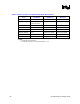
Signal Termination Value Termination
Voltage
Termination
Location
Notes
BPM5DR# Connect to BPM[5]# at the
debug port
NA NA
NOTES:
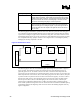
1. The target system resistor connected between VTERM and the PWR pin is part of a voltage division
circuit (see below). The voltage derived from the voltage divider is used as a reference for recovery of
the BPM[5:0]# and RESET# signals on the ITP. The recovery point of the BPM[5:0]# and RESET#
signals can be modified by scaling the target system resistor. The standard 1.5 K 1% target system
resistor will result in a recovery point of 2/3rds of VTERM.
2. Only required if DBA# is used with any target system circuitry. This signal may be left unconnected if
unused.
3. Only required if FBI is used to source a buffer for JTAG TCK. This signal may be left unconnected if
unused.
4. A termination resistor must be located at the receiver of each scan chain agent
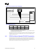
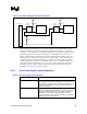
Figure 5. PWR Routing and Usage
1.5K 1%
3.0K 1%
Vterm
ITP 700
Debug Port
Pin PWR
Platform MB
Vpwr
Reset#
+
-
Vpwr
BPM[5:0]#/Reset#
Signals
Recovery
Point
+
-
+
-
.
.
BPM5#
BPM0#
BPM1#
NOTE: By varying the Platform 1.5- K resistor the recovery point could be raised or lowered.
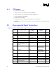
2.3 ITP Signal Layout Guidelines
Routing to the debug port of signals BPM[5:0]# must be shorter than 1.0 ns of electrical length
from the nearest system bus agent. Note that the <1.0 ns requirement applies only to the
BPM[5:0]# trace segments between the debug port and the nearest system bus agent. All other
system bus trace segments must be routed according to the guidelines located in the Platform
Design Guides.