
ITP700 Debug Port Design Guide


R
90 ITP700 Debug Port Design Guide
PASS FAIL Don’t
Care
ISSUE
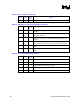
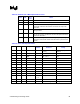
Are the Resistance Values and Termination Voltages Listed in the table
above adhered to?
No bypass condition should allow the Pull-up resistance on TDI to be less
than 150 Ω.
Part 5 – Layout Issues
Below is a list of basic rules to keep in mind when routing the schematics. These guidelines are in
no means comprehensive or serve to replace the recommended layout guidelines in this document.
1. BPM[5:0]# should be routed in matched lengths as full speed Front Side Bus signals. There
should be only two terminations on the trace. One should be a passive resistor located just
beyond the debug port, and the other a passive resistor located just beyond the last agent on
the FSB. Note the flight time of the BPM signals from the closest processor agent on the Front
Side Bus to the debug port. This value will be important later. (Tbpm)
2. BCLK (n,p) should be routed with the same matched length as the clock to the rest of the
processor/chipset agents but with an additional flight time equal to the BPM signals flight
time from the closest processor agent on the front side bus to the debug port (Tbpm). Routing
in this manner will place you close to the optimal recovery point of the BPM#s using BCLK
and its added length. Fine adjustment may be necessary to place BPM# edges in the center of
the ITP Setup and Hold window (400 ps and 500 ps, respectively)
3. TCK should be routed in a star topology from the debug port (or buffer) with matching
lengths to each agent in the scan chain. The FBO feedback from the source of the scan chain
TCK(or FBI) to the ITP should have a flight time equal to the matched TCK paths plus the
flight time of the BPM signals from the closest processor agent on the Front Side Bus to the
debug port (Tbpm). If a buffer is used in the creation of TCK, it is recommended that FBO be
routed from an extra buffer to the FBO pin with a flight time calculated in the same method as
listed above.
4. TMS, like TCK, should also be routed in a star topology from the debug port with matching
lengths to each agent in the scan chain. Ideally these traces will be the same length as those of
TCK to each agent in the scan chain.