
Voltage Regulator Module (VRM) and Enterprise Voltage Regulator-Down (EVRD) 10.0 Design Guidelines


VRM and EVRD 10.0 Design Guidelines
R
10
2 Output Voltage Requirements
2.1 Voltage and Current REQUIRED
A 6-bit VID code provided by the processor to the VRM/EVRD determines a reference output
voltage, as described in Section 3.2. Sections 2.2 and 2.3 specify deviations from the VID
reference voltage.
The load lines in Section 2.2 show the relationship between Vcc and Icc for the processor.
For the Intel® Xeon™ processor with 800MHz system bus, the VRM/EVRD will be required to
support the following:
• A continuous load current (Icc(TDC)) of 85A
• A maximum load current (Icc(Max)) of 100A
• A maximum load current step (Icc(Step)), within a 1 µs period, of 70A
• A maximum current slew rate at the pins of the processor of 560A/µs
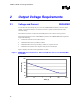
Figure 1 displays the load current requirements over time.
Figure 1. VRM/EVRD 10.0 Load Current vs. Time for Intel® Xeon™ Processor with 800 MHz
System Bus
80
85
90
95
100
105
0.01 0.1 1 10 100 1000
Time (s)
Load Current (A)