
Voltage Regulator Module (VRM) and Enterprise Voltage Regulator-Down (EVRD) 10.0 Design Guidelines

VRM and EVRD 10.0 Design Guidelines
R
20
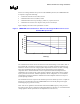
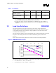
3.3 Differential Remote Sense (VO_SEN+/–) REQUIRED
The PWM controller will include differential sense inputs to compensate for an output voltage
offset of <300 mV in the power distribution path. This common mode voltage is expected to
occur due to transient currents and parasitic inductances and is not expected to be caused by
parasitic resistances. The remote sense lines should draw no more than 10 mA, to minimize offset
errors.
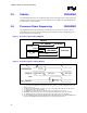
3.4 VRM Present (VRM_pres#) EXPECTED
The VRM should have the VRM_pres# signal. This signal is an output signal used to indicate to
the system that a VRM is plugged into the socket. VRM_pres# is an open-collector/drain or
equivalent signal. Table 6 shows the VRM_pres# pin specification. It is EXPECTED that the
pull-up resistor will be located on the baseboard and will not be integrated into the VRM.
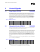
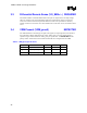
Table 6. VRM_pres# Specifications
Symbol Parameter Min Max Units
I
OL
Output Low Current 0 4 mA
V
OH
Output High Voltage 0.8 5.5 V
V
OL
Output Low Voltage 0 0.4 V