
Voltage Regulator Module (VRM) and Enterprise Voltage Regulator-Down (EVRD) 10.0 Design Guidelines


VRM and EVRD 10.0 Design Guidelines
R
28
7 VRM – Mechanical Guidelines
7.1 VRM Connector EXPECTED
The VRM interface with the baseboard is a 31-pin pair edge connector. The connector uses
latches to hold the VRM in place. Table 9 shows the connector vendors and part numbers.
Table 9. VRM 10.0 Connector Vendor and Part Numbers
Vendor Part Number Notes
Tyco/Amp 1489930-2 1
Foxconn 2EV04607-NW 1
NOTES:
1. These vendors are listed by Intel as a convenience to Intel's general customer base, but Intel does not
make any representations or warranties whatsoever regarding quality, reliability, functionality, or
compatibility of these devices. This list and/or these devices may be subject to change without notice.
7.2 VRM Connector Keying
The connector contains a single notch between pins 10 and 11 (52 and 53 on opposite side) as
shown in Figure 10. This configuration allows both VRM10.0 and VRM 10.1 modules to be
plugged into the connector. The connector footprint key to the baseboard is at pin 57.
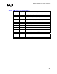
7.3 Pin Descriptions and Assignments
Table 10 shows the VRM10.0 connector pin definitions. The pins that are labeled Reserved
should not be used if there are plans to use VRM10.1 modules with this connector. Those pins are
used on the VRM10.1 module as an additional input voltage pair. Systems that also plan to use
VRM10.1 modules should connect pin 4 to VIN+ and pin 59 to VIN–. See the Voltage Regulator
Module (VRM) and Enterprise Voltage Regulator-Down (EVRD) 10.1 Design Guidelines for
more information. Otherwise those pins can be classified as Unspecified. The pin assignments are
shown in Table 11.