
Voltage Regulator Module (VRM) and Enterprise Voltage Regulator-Down (EVRD) 10.0 Design Guidelines


VRM and EVRD 10.0 Design Guidelines
R
31
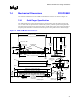
7.4 Mechanical Dimensions PROPOSED
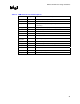
The mechanical dimensions for the VRM 10.0 module and connector are shown in Figure 10.
7.4.1 Gold Finger Specification
The VRM board must contain gold lands (fingers) for interfacing with the VRM connector that
are 1.27 mm ±0.05 mm [0.050 inches ±0.002 inches] wide by 5.08 mm [0.200 inches] minimum
long and spaced 2.54 mm ±0.05 mm [0.100 inches ±0.002 inches] apart. Traces from the lands to
the power plane should be a minimum of 0.89 mm [0.035 inches] wide and of a minimal length.
Figure 10. VRM 10.0 Module and Connector
96.52mm (3.80") MAX
58.42mm
(2.30")
MA X
4.0mm +/-.10
(0.158"+/-.004)
3.0mm (0. 118" ) MIN
80.92mm +/- .05 (3.186" +/-.002)
15.67mm
(0.617")
66.34mm
(2.612")
MA X
50.8mm
(2.0")
Ref .
7.62mm
(0.3") MAX
Component
Keepout
PIN 58PIN 62 PIN 32PIN 53
Vi ew A
Vi ew A
1.07mm+/-0.05
(0.042"+/-.002)
TYP
PIN 53
7.62mm
(0.30")
MIN
1.27mm+/-0.05
(0.05" +/-.002)
TYP
PCB Footprint
5.08mm
(0.200")
PIN 1
2.54mm
(0.10")
PIN 62 PIN 32
10.16mm
(0.4")
MA X
14.27mm
(0.562")
MA X
0.52mm
(.020")
1.57mm +/- 0.20
(.062" +/-.008)
PCB
Edge Car d
Contacts
5.08mm
(0.20")
30
23.78mm
(0.936")
17.78mm
(0.70")
OPEN Latches 113.0mm (4.449") MAX
CLOSED Latches 97.10mm ( 3.823") MAX
9.60mm
(0.378")
MA X
NEAR SIDE Components
FA R SIDE Components
PIN 1
PIN 62
hole diameter
1.02+/-0.08mm
(.040+/-.003")