
Voltage Regulator Module (VRM) and Enterprise Voltage Regulator-Down (EVRD) 10.1 Design Guidelines


Voltage Regulator Module (VRM) and Enterprise Voltage 29
Regulator-Down (EVRD) 10.1 Design Guidelines
7 VRM – Mechanical Guidelines
7.1 VRM Connector - EXPECTED
The part number and vendor name for the connector can be found in Table 7-1. The VRM interface
with the system board is a 31-pin pair edge connector. The connector uses latches to hold the VRM
in place. The connector will be rated to handle a continuous load current of 115 A.
NOTE:
1. These vendors are listed by Intel as a convenience to Intel's general customer base, but Intel does not make
any representations or warranties whatsoever regarding quality, reliability, functionality, or compatibility of
these devices. This list and/or these devices may be subject to change without notice.
7.2 VRM Connector Keying
7.2.1 Connector Keying
• Single notch between pins 5 and 6 (57 and 58 opposite side).
• Single notch between pins 10 and 11 (52 and 53 opposite side).
• Connector footprint key at pin 57.
7.2.2 Connector Pin 1 Orientation
Referencing Figure 7-1, Outline Drawing, Near Side (NS) pins sequence 1 through 31, left to right.
Far Side (FS) pins sequence 32 through 62. Pin 1 and 62 are opposite one another.
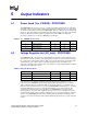
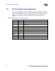
Table 7-1. VRM10.1 Connector Part Number and Vendor Name
Connector Vendor Part Number Note
Tyco/Amp 1489930-1 1
Foxconn 2EV04507-NW 1