
VRM 9.1 DC-DC Converter Design Guidelines
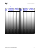
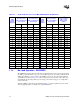
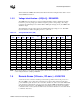

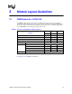
Table Of Contents
- 1 Electrical Specifications
- 1.1 Output Requirements
- 1.1.1 Voltage and Current - REQUIRED
- 1.1.2 Maximum Ratings - EXPECTED
- 1.1.3 Output Voltage Tolerance - REQUIRED
- 1.1.4 No-Load Operation - REQUIRED
- 1.1.5 Turn-on Response Time - EXPECTED
- 1.1.6 Overshoot and Undershoot at Turn-On or Turn-Off - REQUIRED
- 1.1.7 Converter Stability - REQUIRED
- 1.1.8 Current Sharing - REQUIRED
- 1.2 Input Voltage and Current
- 1.3 Control Inputs - REQUIRED
- 1.4 Remote Sense (VO-sen+, VO-sen-) - EXPECTED
- 1.5 Power Good Output (PWRGD) - REQUIRED
- 1.6 VRM Present (VRM-pres) - EXPECTED
- 1.7 Efficiency - PROPOSED
- 1.8 Isolation - PROPOSED
- 1.9 Fault Protection
- 1.1 Output Requirements
- 2 Module Layout Guidelines
- 3 Environmental Conditions
- 3.1 Operating Temperature - PROPOSED
- 3.2 VRM Board Temperature - REQUIRED
- 3.3 Non-Operating Temperature - PROPOSED
- 3.4 Humidity - PROPOSED
- 3.5 Altitude - PROPOSED
- 3.6 Electrostatic Discharge - PROPOSED
- 3.7 Shock and Vibration - PROPOSED
- 3.8 Electromagnetic Compatibility - PROPOSED
- 3.9 Reliability - PROPOSED
- 3.10 Safety - PROPOSED

VRM 9.1 DC-DC Converter Design Guidelines 17
Electrical Specifications
1.8 Isolation - PROPOSED
Isolation from input to output is optional. A transformer-based topology may have advantages over
a non-isolated buck converter: Over-voltage due to a shorted FET is eliminated, and duty cycles
can be optimized to simplify control or improve efficiency. A common ground between input and
output is required with an isolated topology.
1.9 Fault Protection
These features are built into the VRM to prevent damage to the VRM or the circuits it powers.
1.9.1 Over Voltage Protection - EXPECTED
The VRM should provide over-voltage protection (OVP) by including a circuit, separate from the
voltage sense path, capable of shutting off the output drive when the output voltage rises beyond
Vtrip. If practical, the protection circuit should also enable a low-resistance path to ground, so that
no single component failure results in the output voltage rising above Vtrip. A non-resettable or
resettable fuse may be included in the input of the VRM for this function. The response time should
be such that the output voltage will not exceed VID plus 250 mV.
Minimum Vtrip should be:
• The VID set-point voltage
• plus 55 mV to compensate for remote sense
• plus margin to prevent false trips.
Maximum Vtrip should be VID plus 250 mV.
No combination of input voltage or output load sequences should falsely trigger an OVP event.
1.9.2 Fuse Protection for Power Input - EXPECTED
The power input (12 V) should be protected with a fuse rated not greater than 30 A, which sustains
all operating and inrush conditions and which “trips” only on catastrophic failure of the converter.
1.9.3 Overload Protection - EXPECTED
The VRM should be capable of withstanding a continuous, abnormally low resistance on the output
without damage or over-stress to the unit. Output current under this condition will be limited to no
more than 150% of the maximum rated output of the VRM. Latching off or hiccup mode is
acceptable during over-current conditions. The VRM should be capable of starting into a constant
current load of 50% of maximum rated load current with maximum load capacitance, as defined in
Section 1.1.7, without tripping the OCP circuitry. Errors in current sharing (see Section 1.1.8)
during startup should not cause OCP circuits to shut down the converter.