
VRM 9.1 DC-DC Converter Design Guidelines
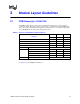
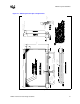
Table Of Contents
- 1 Electrical Specifications
- 1.1 Output Requirements
- 1.1.1 Voltage and Current - REQUIRED
- 1.1.2 Maximum Ratings - EXPECTED
- 1.1.3 Output Voltage Tolerance - REQUIRED
- 1.1.4 No-Load Operation - REQUIRED
- 1.1.5 Turn-on Response Time - EXPECTED
- 1.1.6 Overshoot and Undershoot at Turn-On or Turn-Off - REQUIRED
- 1.1.7 Converter Stability - REQUIRED
- 1.1.8 Current Sharing - REQUIRED
- 1.2 Input Voltage and Current
- 1.3 Control Inputs - REQUIRED
- 1.4 Remote Sense (VO-sen+, VO-sen-) - EXPECTED
- 1.5 Power Good Output (PWRGD) - REQUIRED
- 1.6 VRM Present (VRM-pres) - EXPECTED
- 1.7 Efficiency - PROPOSED
- 1.8 Isolation - PROPOSED
- 1.9 Fault Protection
- 1.1 Output Requirements
- 2 Module Layout Guidelines
- 3 Environmental Conditions
- 3.1 Operating Temperature - PROPOSED
- 3.2 VRM Board Temperature - REQUIRED
- 3.3 Non-Operating Temperature - PROPOSED
- 3.4 Humidity - PROPOSED
- 3.5 Altitude - PROPOSED
- 3.6 Electrostatic Discharge - PROPOSED
- 3.7 Shock and Vibration - PROPOSED
- 3.8 Electromagnetic Compatibility - PROPOSED
- 3.9 Reliability - PROPOSED
- 3.10 Safety - PROPOSED

Environmental Conditions
24 VRM 9.1 DC-DC Converter Design Guidelines
3.5 Altitude - PROPOSED
• 10 k feet – operating
• 50 k feet – non-operating
3.6 Electrostatic Discharge - PROPOSED
Testing should be in accordance with IEC 61000-4-2.
Operating – 15 kV initialization level. The direct ESD event should cause no out-of-regulation
conditions – including overshoot, undershoot and nuisance trips of over-voltage protection, over-
current protection or remote shutdown circuitry.
Non-operating - 25 kV initialization level. The direct ESD event should not cause damage to VRM
circuitry.
3.7 Shock and Vibration - PROPOSED
The VRM should not be damaged and the interconnect integrity not compromised during:
A shock of 50 G with an 11 millisecond half sine wave, non-operating, the shock to be applied in
each of the orthogonal axes.
Vibration of 0.01 G² per Hz at 5 Hz, sloping to 0.02 G² per Hz at 20 Hz and maintaining 0.02 G² per
Hz from 20 Hz to 500 Hz, non-operating, applied in each of the orthogonal axes.
3.8 Electromagnetic Compatibility - PROPOSED
Design, including materials, should be consistent with the manufacture of units that comply with
the limits of FCC Class B and CISPR22 Class B for radiated emissions.
3.9 Reliability - PROPOSED
Design, including materials, should be consistent with the manufacture of units with an MTBF of
500,000 hours of continuous operation at 55° C maximum, outputs loaded and worst-case line,
while meeting specified requirements. MTBF should be calculated in accordance with
MIL-STD-217F or Bellcore.
3.10 Safety - PROPOSED
The VRM should be UL Recognized to standard UL1950 3rd Ed., including requirements of
IEC950 and EN 60950. Plastic parts and printed wiring board are to be UL Recognized with 94V-0
flame class.
§