
VRM 9.1 DC-DC Converter Design Guidelines

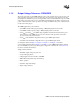
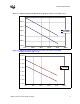
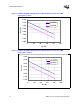
Table Of Contents
- 1 Electrical Specifications
- 1.1 Output Requirements
- 1.1.1 Voltage and Current - REQUIRED
- 1.1.2 Maximum Ratings - EXPECTED
- 1.1.3 Output Voltage Tolerance - REQUIRED
- 1.1.4 No-Load Operation - REQUIRED
- 1.1.5 Turn-on Response Time - EXPECTED
- 1.1.6 Overshoot and Undershoot at Turn-On or Turn-Off - REQUIRED
- 1.1.7 Converter Stability - REQUIRED
- 1.1.8 Current Sharing - REQUIRED
- 1.2 Input Voltage and Current
- 1.3 Control Inputs - REQUIRED
- 1.4 Remote Sense (VO-sen+, VO-sen-) - EXPECTED
- 1.5 Power Good Output (PWRGD) - REQUIRED
- 1.6 VRM Present (VRM-pres) - EXPECTED
- 1.7 Efficiency - PROPOSED
- 1.8 Isolation - PROPOSED
- 1.9 Fault Protection
- 1.1 Output Requirements
- 2 Module Layout Guidelines
- 3 Environmental Conditions
- 3.1 Operating Temperature - PROPOSED
- 3.2 VRM Board Temperature - REQUIRED
- 3.3 Non-Operating Temperature - PROPOSED
- 3.4 Humidity - PROPOSED
- 3.5 Altitude - PROPOSED
- 3.6 Electrostatic Discharge - PROPOSED
- 3.7 Shock and Vibration - PROPOSED
- 3.8 Electromagnetic Compatibility - PROPOSED
- 3.9 Reliability - PROPOSED
- 3.10 Safety - PROPOSED
VRM 9.1 DC-DC Converter Design Guidelines 7
1 Electrical Specifications
1.1 Output Requirements
1.1.1 Voltage and Current - REQUIRED
The VRM 9.1 Voltage Regulator Module is a DC-DC converter that supplies the correct voltage
and current to a single processor, or when paralleled with other like converters, supplies the
required voltage and current to multiple processors, whose Vcc and Vss or V
CACHE
and Vss are
also connected in parallel.
One VRM per processor is assumed for Intel
®
Xeon™ processor with 512 KByte L2 cache and one
VRM per two processor cache for 64-bit Intel
®
Xeon™ processor MP. Current requirements are
shown in Table 1-1. The maximum output voltage is determined by the five-bit VID code provided
to the VRM, as described in Section 1.3.2. The system baseboard must supply additional
decoupling capacitance and sufficient power and ground plane area to properly carry the DC
currents. The required V-I relationship for the Intel
®
Xeon™ processor is given in Figure 1-1, the
one for the Intel Xeon processor with 512 KByte L2 cache is in Figure 1-2 and the ones for the
64-bit Intel Xeon processor MP in Figure 1-3 and Figure 1-4.
Processor data is shown for reference. The corresponding processor data sheet takes precedence
for processor specifications.
1.1.2 Maximum Ratings - EXPECTED
To supply the anticipated requirements of the planned processor versions, VRM 9.1 should be able
to provide a sustained output current of 81 A. Refer to Table 1-1 for maximum design parameters.
NOTES:
1. Estimate of lowest current state for VRM regulation, not to be construed as a processor specification. Refer
to data sheet for actual design information.
2. Includes tolerance for needs of current sharing
3. Typical value for slew rate. Actual requirement will depend on decoupling of actual VRM and baseboard.
Slew rate of processor load at the socket is 450 A/µs.
Table 1-1. VRM 9.1 Current Requirements
Symbol Parameter Unit Value
Icc
MIN
Minimum current drawn by a single processor A 0.5
1
Icc
ACTIVE
Maximum step current change by a single processor A 54
Icc
MAX
Maximum total current drawn by a single processor A 75
Ivrm
MAX
Maximum current required
2
A81
Ivrm
SLEW
VRM output current slew rate
3
A/µs50