Intel® Pentium® M Processor on 90 nm Process with 2-MB L2 Cache Datasheet January 2006 Document Number: 302189-008
IINFORMATION IN THIS DOCUMENT IS PROVIDED IN CONNECTION WITH INTEL® PRODUCTS. NO LICENSE, EXPRESS OR IMPLIED, BY ESTOPPEL OR OTHERWISE, TO ANY INTELLECTUAL PROPERTY RIGHTS IS GRANTED BY THIS DOCUMENT.
Contents 1 Introduction.................................................................................................................................... 7 1.1 1.2 2 Low Power Features.................................................................................................................... 11 2.1 2.2 2.3 2.4 3 3.2 3.3 3.4 3.5 3.6 3.7 3.8 3.9 Power and Ground Pins...................................................................................................... 17 3.1.
Figures 2-1 Clock Control States................................................................................................................... 11 3-1 Illustration of Active State VCC Static and Ripple Tolerances (HFM- VID#A)............................ 31 3-2 Illustration of Deep Sleep State VCC Static and Ripple Tolerances (LFM- VID#A) ................... 32 3-3 Illustration of Active State VCC Static and Ripple Tolerances (HFM- VID#B)............................
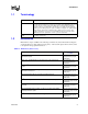
Tables 1-1 References ................................................................................................................................... 9 3-1 Voltage Identification Definition .................................................................................................. 18 3-2 FSB Pin Groups.......................................................................................................................... 20 3-3 Processor DC Absolute Maximum Ratings...............................
Revision History Revision 001 002 Description Initial release of datasheet ® 003 • • 004 May 2004 ® Added Intel Pentium M processor 725 and 715 specifications • Date ® June 2004 ® Specifications of Intel Pentium M processor Low Voltage 738 and Ultra Low Voltage 733 & 723 added in chapter 3 and chapter 5. Chapter 2 section 2.1.3 - Missing Stop Grant State title added. Description was previously merged with Auto Halt state section and is unchanged.
Introduction 1 Introduction The Intel® Pentium® M processor based on 90 nm process technology featuring 2-MB L2 cache and 400-MHz front side bus (FSB) is the next generation high- performance, low-power mobile processor based on the Intel® Pentium® processor architecture.
Introduction architecture enable significant performance improvement over existing mobile processors. The processor’s data prefetch logic fetches data to the L2 cache before L1 cache requests occurs, resulting in reduced bus cycle penalties and improved performance. The streaming SIMD extensions 2 (SSE2) enable break-through levels of performance in multimedia applications including 3-D graphics, video decoding/encoding, and speech recognition.
Introduction 1.1 Terminology Term 1.2 Definition # A “#” symbol after a signal name refers to an active low signal, indicating a signal is in the active state when driven to a low level. For example, when RESET# is low, a reset has been requested. Conversely, when NMI is high, a nonmaskable interrupt has occurred. In the case of signals where the name does not imply an active state but describes part of a binary sequence (such as address or data), the “#” symbol implies that the signal is inverted.
Introduction Table 1-1. References (Sheet 2 of 2) Document IA-32 Intel® Architecture Software Developer's Manual Volume 1: Basic Architecture Document Number/ Location1 http://www.intel.com/ design/pentium4/ manuals/index_new.htm Volume 2A: Instruction Set Reference Volume 2B: Instruction Set Reference Volume 3: System Programming Guide NOTE: Contact your Intel representative for the latest revision and document number of this document.
Low Power Features 2 Low Power Features 2.1 Clock Control and Low Power States The Pentium M processor supports the AutoHALT Power-Down, Stop Grant, Sleep, Deep Sleep, and Deeper Sleep states for optimal power management. See Figure 2-1 for a visual representation of the processor low-power states. Figure 2-1.
Low Power Features The system can generate a STPCLK# while the processor is in the AutoHALT Power-Down state. When the system deasserts the STPCLK# interrupt, the processor will return execution to the HALT state. While in AutoHALT Power-Down state, the processor will process bus snoops and interrupts. 2.1.
Low Power Features 2.1.5 Sleep State A low power state in which the processor maintains its context, maintains the phase-locked loop (PLL), and has stopped all internal clocks. The Sleep state can be entered only from Stop-Grant state. Once in the Stop-Grant state, the processor will enter the Sleep state upon the assertion of the SLP# signal. The SLP# pin should only be asserted when the processor is in the Stop Grant state.
Low Power Features 2.1.7 Deeper Sleep State The Deeper Sleep state is the lowest power state the processor can enter. This state is functionally identical to the Deep Sleep state but at a lower core voltage. The control signals to the voltage regulator to initiate a transition to the Deeper Sleep state are provided on the platform. Please refer to the platform design guides listed in Table 1-1. 2.2 Enhanced Intel SpeedStep® Technology The Pentium M processor features Enhanced Intel SpeedStep technology.
Low Power Features 2.3 Front Side Bus Low Power Enhancements The Pentium M processor incorporates the following front side bus (processor system bus) low power enhancements: • • • • Dynamic FSB Power Down BPRI# control for address and control input buffers Dynamic On Die Termination disabling Low VCCP (I/O termination voltage) The Pentium M processor incorporates the DPWR# signal that controls the data bus input buffers on the processor.
Low Power Features 16 Datasheet
Electrical Specifications 3 Electrical Specifications 3.1 Power and Ground Pins For clean, on-chip power distribution, the Pentium M processor has a large number of VCC (power) and VSS (ground) inputs. All power pins must be connected to VCC power planes while all VSS pins must be connected to system ground planes. Use of multiple power and ground planes is recommended to reduce I*R drop. Please refer to the platform design guides for more details.
Electrical Specifications Table 3-1. Voltage Identification Definition VID 3.3 5 4 3 2 1 0 0 0 0 0 0 0 0 0 0 0 0 1 0 0 0 0 1 0 0 0 0 0 0 0 0 0 0 VCC V VID VCC V 5 4 3 2 1 0 1.708 1 0 0 0 0 0 1.196 1.692 1 0 0 0 0 1 1.180 0 1.676 1 0 0 0 1 0 1.164 1 1 1.660 1 0 0 0 1 1 1.148 1 0 0 1.644 1 0 0 1 0 0 1.132 0 1 0 1 1.628 1 0 0 1 0 1 1.116 0 0 1 1 0 1.612 1 0 0 1 1 0 1.100 0 0 0 1 1 1 1.
Electrical Specifications 3.4 Signal Terminations and Unused Pins All RSVD (RESERVED) pins must remain unconnected. Connection of these pins to VCC, VSS, or to any other signal (including each other) can result in component malfunction or incompatibility with future Pentium M processors. See Section 4.2 for a pin listing of the processor and the location of all RSVD pins. For reliable operation, always connect unused inputs or bidirectional signals to an appropriate signal level.
Electrical Specifications Table 3-2. FSB Pin Groups Signal Group Signals1 Type AGTL+ Common Clock Input Synchronous to BCLK[1:0] BPRI#, DEFER#, DPWR#, PREQ#, RESET#, RS[2:0]#, TRDY# AGTL+ Common Clock I/O Synchronous to BCLK[1:0] ADS#, BNR#, BPM[3:0]#, BR0#, DBSY#, DRDY#, HIT#, HITM#, LOCK#, PRDY# AGTL+ Source Synchronous I/O Synchronous to assoc.
Electrical Specifications 3.8 Maximum Ratings Table 3-3 lists the processor’s maximum environmental stress ratings. The processor should not receive a clock while subjected to these conditions. Functional operating parameters are listed in the AC and DC tables. Extended exposure to the maximum ratings may affect device reliability.
Electrical Specifications Table 3-4. Voltage and Current Specifications - Standard Voltage Processors (Sheet 1 of 2) Symbol VCCD765 VCCD755 VCCD745 22 Parameter VID#A Typical VID#B Typical VID#C Typical VID#D Typical VID#E Typical Intel® Pentium® M Processor 765 Core VCC FOR Enhanced Intel SpeedStep® Technology Operating Points: 2.1 GHz 1.340 1.324 1.308 1.356 1.8 GHz 1.276 1.260 1.244 1.292 1.6 GHz 1.228 1.212 1.212 1.244 1.4 GHz 1.180 1.180 1.164 1.196 1.2 GHz 1.132 1.
Electrical Specifications Table 3-4. Voltage and Current Specifications - Standard Voltage Processors (Sheet 2 of 2) Symbol VCCD735 VCCD725 VCCD715 Parameter VID#A Typical VID#B Typical VID#C Typical VID#D Typical Pentium M Processor 735 Core VCC for Enhanced Intel SpeedStep Technology Operating Points: 1.7 GHz 1.340 1.324 1.308 1.276 1.4 GHz 1.244 1.244 1.228 1.212 1.2 GHz 1.180 1.180 1.164 1.148 1.0 GHz 1.116 1.116 1.116 1.100 800 MHz 1.052 1.052 1.052 1.052 600 MHz 0.
Electrical Specifications Table 3-5. Voltage and Current Specifications - Low Voltage Processors (Sheet 1 of 2) Symbol VCCD778 VCCD758 24 Parameter Min Typ Intel® Pentium® M Processor, Low Voltage 778 Core VCC for Enhanced Intel SpeedStep® Technology Operating Points: 1.6 GHz 1.116 1.5 GHz 1.116 1.4 GHz 1.100 1.3 GHz 1.084 1.2 GHz 1.068 1.1 GHz 1.052 1.0 GHz 1.052 900 GHz 1.036 800 MHz 1.020 600 MHz 0.
Electrical Specifications Table 3-5. Voltage and Current Specifications - Low Voltage Processors (Sheet 2 of 2) Symbol VCCD738 Parameter Min Typ Max Unit V Pentium M Processor, Low Voltage, 738 Core VCC for Enhanced Intel SpeedStep Technology Operating Points: 1.4 GHz 1.116 1.3 GHz 1.116 1.2 GHz 1.100 1.1 GHz 1.068 1.0 GHz 1.052 900 GHz 1.036 800 MHz 1.020 600 MHz 0.988 Note 1, 2 NOTES: 1. The typical values shown are the VID encoded voltages.
Electrical Specifications Table 3-6. Voltage and Current Specifications - Ultra Low Voltage Processors (Sheet 1 of 2) Symbol Parameter VCCD773 Intel® Pentium® M Processor, Ultra Low Voltage, 773 Core VCC for Enhanced Intel SpeedStep® Technology Operating Points: VCCD753 VCCD733J 26 Min Typ Max VID# GTyp VID# HTyp VID#I Typ VID# J Typ VID# K Typ VID# L Typ 1.3 GHz 0.956 0.940 0.924 0.908 0.892 0.876 1.2 GHz 0.940 0.924 0.908 0.908 0.892 0.876 1.1 GHz 0.924 0.908 0.892 0.
Electrical Specifications Table 3-6. Voltage and Current Specifications - Ultra Low Voltage Processors (Sheet 2 of 2) Symbol Parameter VCCD733 Pentium M Processor, Ultra Low Voltage, 733 Core VCC for Enhanced Intel SpeedStep Technology Operating Points: VCCD723 Min Typ 1.1 GHz 0.940 1.0 GHz 0.924 900 MHz 0.892 800 MHz 0.876 600 MHz 0.812 Pentium M Processor, Ultra Low Voltage, 723 Core VCC for Enhanced Intel SpeedStep Technology Operating Points: 1.0 GHz 0.940 900 MHz 0.908 800 MHz 0.
Electrical Specifications Table 3-7. Voltage and Current Specifications (Continued) (Sheet 1 of 3) Symbol Min Typ Max Unit Note VCC,BOOT Default VCC Voltage for Initial Power-Up 1.14 1.20 1.26 V 2 VCCP AGTL+ Termination voltage 0.997 1.05 1.102 V 2 VCCA PLL Supply Voltage 1.71 1.8 1.89 V 2, VCCA for 778, 758, 738 and 753,733J, 733, 723 PLL Supply Voltage for Pentium M Processors V 2, 8 778/758/738 1.71 1.8 1.89 753/733J/733/723 1.425 1.5 1.
Electrical Specifications Table 3-7. Voltage and Current Specifications (Continued) (Sheet 2 of 3) Symbol IAH, ISGNT ISLP IDSLP Datasheet Parameter Min Typ Max ICC Auto-Halt & StopGrant for Pentium M Processors: 765/755/745/778/758/738/ 735/725/715 at LFM Vcc 6.0 765/755/745/735/725/715 at HFM Vcc 15.1 778/758/738 at HFM Vcc 6.4 773/753/733J at LFM Vcc 2.3 733/723 at LFM Vcc 2.1 773/753/733J HFM Vcc 3.3 733/723 at HFM Vcc 3.
Electrical Specifications Table 3-7. Voltage and Current Specifications (Continued) (Sheet 3 of 3) Symbol IDPRSLP1 IDPRSLP1 Parameter Min Typ Max ICC Deeper Sleep @ 0.748 V for Pentium M Processors: 765/755/745/778/758/738/ 735/725/715 2.5 753/733J/733/723 1.6 ICC Deeper Sleep @ 0.726 V for Pentium M Processors: Unit Note A 4, 9, 10 A 4, 9, 10 765/755/745/778/758/738/ 735/725/715 2.3 753/733J/733/723 1.3 dICC/DT VCC power supply current slew rate 0.
Electrical Specifications Table 3-8. Voltage Tolerances for the Intel® Pentium® M Processor (Active State) VID#A Highest Frequency Mode: VID=1.340V, Offset=0% ACTIVE MODE ICC, A VCC, V STATIC Min Max Lowest Frequency Mode: VID=0.988V, Offset=0% Ripple Min Max ICC, A VCC, V STATIC Min Max Ripple Min Max 0 1.340 1.320 1.360 1.310 1.370 0.0 0.988 0.973 1.003 0.963 1.013 0.9 1.337 1.317 1.357 1.307 1.367 0.4 0.987 0.972 1.002 0.962 1.012 1.9 1.334 1.314 1.355 1.304 1.
Electrical Specifications Table 3-9. Voltage Tolerances for the Intel® Pentium® M Processor (Deep Sleep State) VID#A Highest Frequency Mode: VID=1.340V, Offset=-1.2% Deep Sleep MODE STATIC Ripple ICC, A VCC, V Min Max Min Max 0.0 1.324 1.304 1.344 1.294 0.9 1.321 1.301 1.341 1.9 1.318 1.298 2.8 1.315 1.295 3.8 1.313 4.7 Lowest Frequency Mode: VID=0.988V, Offset=-1.2% STATIC Ripple ICC, A VCC, V Min Max Min Max 1.354 0.0 0.976 0.961 0.991 0.951 1.001 1.291 1.
Electrical Specifications Table 3-10. Voltage Tolerances for the Intel® Pentium® M Processor (Active State) VID#B Highest Frequency Mode: VID=1.324V, Offset=0% ACTIVE MODE ICC, A V CC, V STATIC Min Max Lowest Frequency Mode: VID=0.988V, Offset=0% Ripple Min Max ICC, A V CC, V STATIC Min Max Ripple Min Max 0 1.324 1.304 1.344 1.294 1.354 0.0 0.988 0.973 1.003 0.963 1.013 0.9 1.321 1.301 1.341 1.291 1.351 0.4 0.987 0.972 1.002 0.962 1.012 1.9 1.318 1.299 1.338 1.
Electrical Specifications Table 3-11. Voltage Tolerances for the Intel® Pentium® M Processor (Deep Sleep State) VID#B Highest Frequency Mode: VID=1.324V, Offset=-1.2% Deep Sleep MODE ICC, A VCC, V 0.0 0.9 STATIC Ripple Lowest Frequency Mode: VID=0.988V, Offset=-1.2% ICC, A VCC, V 1.338 0.0 1.335 0.4 1.273 1.332 1.319 1.270 1.317 1.267 1.274 1.314 1.291 1.271 6.6 1.288 7.6 1.285 8.5 9.5 Min Max Min Max 1.308 1.288 1.328 1.278 1.305 1.285 1.325 1.275 1.9 1.302 1.
Electrical Specifications Table 3-12. Voltage Tolerances for the Intel® Pentium® M Processor (Active State) VID#C Highest Frequency Mode: VID=1.308V, Offset=0% ACTIVE MODE ICC, A VCC, V STATIC Min Max Ripple Min Max Lowest Frequency Mode: VID=0.988V, Offset=0% ICC, A V CC, V STATIC Min Max Ripple Min Max 0 1.308 1.288 1.328 1.278 1.338 0.0 0.988 0.973 1.003 0.963 1.013 0.9 1.305 1.286 1.325 1.276 1.335 0.4 0.987 0.972 1.002 0.962 1.012 1.9 1.302 1.283 1.322 1.273 1.
Electrical Specifications Table 3-13. Voltage Tolerances for the Intel® Pentium® M Processor (Deep Sleep State) VID#C Highest Frequency Mode: VID=1.308V, Offset=-1.2% Deep Sleep MODE ICC, A VCC, V 0.0 0.9 STATIC Ripple Lowest Frequency Mode: VID=0.988V, Offset=-1.2% ICC, A VCC, V 1.322 0.0 1.319 0.4 1.257 1.316 1.254 1.313 1.301 1.251 1.258 1.298 1.256 1.295 1.272 1.253 7.6 1.270 8.5 1.267 9.5 Min Max Min Max 1.292 1.273 1.312 1.263 1.289 1.270 1.309 1.260 1.9 1.
Electrical Specifications Table 3-14. Voltage Tolerances for the Intel® Pentium® M Processor (Active State) VID#D Highest Frequency Mode: VID=1.276V, Offset=0% ACTIVE MODE I CC , A V CC , V STATIC Min Max Ripple Min Max Lowest Frequency Mode: VID=0.988V, Offset=0% ICC , A V CC , V STATIC Min Max Ripple Min Max 0 1.276 1.257 1.295 1.247 1.305 0.0 0.988 0.973 1.003 0.963 1.013 0.9 1.273 1.254 1.292 1.244 1.302 0.4 0.987 0.972 1.002 0.962 1.012 1.9 1.270 1.251 1.290 1.
Electrical Specifications Table 3-15. Voltage Tolerances for the Intel® Pentium® M Processor (Deep Sleep State) VID#D Lowest Frequency Mode: VID=0.988V, Offset=-1.2% Highest Frequency Mode: VID=1.276V, Offset=-1.2% Deep Sleep MODE STATIC Ripple ICC, A VCC, V Min Max Min Max 0.0 1.261 1.242 1.280 1.232 0.9 1.258 1.239 1.277 1.9 1.255 1.236 1.274 2.8 1.252 1.233 3.8 1.249 1.230 4.7 1.246 5.7 6.6 STATIC Ripple ICC, A VCC, V Min Max Min Max 1.290 0.0 0.976 0.961 0.
Electrical Specifications Table 3-16. Voltage Tolerances for the Intel® Pentium® M Processor (Active State) VID#E Highest Frequency Mode: VID=1.356V, Offset=0% ACTIVE MODE I CC , A V CC , V STATIC Min Max Lowest Frequency Mode: VID=0.988V, Offset=0% Ripple Min Max ICC , A V CC , V STATIC Min Max Ripple Min Max 0 1.356 1.336 1.376 1.326 1.386 0.0 0.988 0.973 1.003 0.963 1.013 0.9 1.353 1.333 1.374 1.323 1.384 0.4 0.987 0.972 1.002 0.962 1.012 1.9 1.350 1.330 1.371 1.
Electrical Specifications Table 3-17. Voltage Tolerances for the Intel® Pentium® M Processor (Deep Sleep State) VID#E Lowest Frequency Mode: VID=0.988V, Offset=-1.2% Highest Frequency Mode: VID=1.356V, Offset=-1.2% Deep Sleep MODE STATIC Ripple ICC, A VCC, V Min Max Min Max 0.0 1.340 1.319 1.360 1.309 0.9 1.337 1.317 1.357 1.9 1.334 1.314 1.354 2.8 1.331 1.311 3.8 1.328 1.308 4.7 1.326 5.7 STATIC Ripple ICC, A VCC, V Min Max Min Max 1.370 0.0 0.976 0.961 0.
Electrical Specifications Table 3-18. Voltage Tolerances for the Intel® Pentium® M Processor LV (Active State) Highest Frequency Mode: VID=1.116V, Offset=0% ACTIVE MODE Datasheet ICC, A VCC, V STATIC Min Max Ripple Min Max Lowest Frequency Mode: VID=0.988V, Offset=0% ICC, A VCC, V STATIC Min Max Ripple Min Max 0 1.116 1.099 1.133 1.089 1.143 0.0 0.988 0.973 1.003 0.963 1.013 0.4 1.115 1.098 1.131 1.088 1.141 0.4 0.987 0.972 1.002 0.962 1.012 0.9 1.113 1.097 1.130 1.
Electrical Specifications Table 3-19. Voltage Tolerances for the Intel® Pentium® M Processor LV (Deep Sleep State) Highest Frequency Mode: VID=1.116V, Offset=-1.2% Deep Sleep MODE ICC, A VCC, V 0.0 STATIC Ripple Lowest Frequency Mode: VID=0.988V, Offset=-1.2% ICC, A VCC, V 1.129 0.0 1.075 1.128 1.073 1.127 1.116 1.072 1.081 1.114 1.097 1.080 2.4 1.095 2.8 Min Max Min Max 1.103 1.086 1.119 1.076 0.4 1.101 1.085 1.118 0.8 1.100 1.083 1.117 1.2 1.099 1.082 1.6 1.
Electrical Specifications Table 3-21. Voltage Tolerances for the Intel® Pentium® M Processor ULV (Deep Sleep State) Highest Frequency Mode: VID=0.940V, Offset=-1.2% Deep Sleep MODE ICC, A VCC, V 0.0 0.2 STATIC Lowest Frequency Mode: VID=0.812V, Offset=-1.2% Ripple ICC, A VCC, V 0.953 0.0 0.952 0.1 0.903 0.952 0.941 0.903 0.912 0.940 0.912 0.940 0.925 0.911 1.4 0.925 1.6 1.8 Min Max Min Max 0.929 0.915 0.943 0.905 0.928 0.914 0.942 0.904 0.4 0.928 0.913 0.942 0.
Electrical Specifications Figure 3-12. Deep Sleep VCC and ICC Load Line VCC [V] Slope= -3.0 mV/A 10mV= RIPPLE Vcc nom {HFM | LFM} - 1.2% +/-1.5% from Nominal =VR Error 0 I CC [A] I CC max Deep Sleep {HFM | LFM} Table 3-22. FSB Differential BCLK Specifications Symbol Parameter Min Typ Max Notes1 VL Input Low Voltage VH Input High Voltage 0.660 0.710 0.850 V VCROSS Crossing Voltage 0.25 0.35 0.55 V 2 Range of Crossing Points N/A N/A 0.
Electrical Specifications Table 3-23. AGTL+ Signal Group DC Specifications Symbol Parameter Min Typ Max Unit Notes1 VCCP I/O Voltage 0.997 1.05 1.102 V GTLREF Reference Voltage 2/3 VCCP 2% 2/3 VCCP 2/3 VCCP + 2% V 6 VIH Input High Voltage GTLREF+0.1 VCCP+0.1 V 3,6 VIL Input Low Voltage -0.1 GTLREF-0.1 V 2,4 VOH Output High Voltage RTT Termination Resistance RON Buffer On Resistance ILI Input Leakage Current Cpad Pad Capacitance VCCP 6 47 55 63 Ω 7 17.7 24.
Electrical Specifications Table 3-25. Open Drain Signal Group DC Specifications Min Typ Max Unit Notes1 V 3 Symbol Parameter VOH Output High Voltage VOL Output Low Voltage 0 0.20 V IOL Output Low Current 16 50 mA 2 ILO Leakage Current ± 200 µA 4 Cpad Pad Capacitance 3.0 pF 5 VCCP 1.7 2.3 1. Unless otherwise noted, all specifications in this table apply to all processor frequencies. 2. Measured at 0.2 V. 3.
Package Mechanical Specifications and Pin Information 4 Package Mechanical Specifications and Pin Information The Pentium M Processor is available in 478-pin, Micro-FCPGA and 479-ball, Micro-FCBGA packages. Different views of the Micro-FCPGA package are shown in Figure 4-1 through Figure 4-3. Package dimensions are shown in Table 4-1. Different views of the Micro-FCBGA package are shown in Figure 4-4 through Figure 4-6. Package dimensions are shown in Table 4-2.
Package Mechanical Specifications and Pin Information Figure 4-2. Micro-FCPGA Package - Top and Side Views SUBSTRATE KEEPO UT ZO NE DO NO T CONTACT PACKAG E IN S ID E T H IS L IN E 7 (K 1) 8 p la ce s 5 (K) 4 p la ce s 0 .2 8 6 A 1 .2 5 M A X (A 3) D1 3 5 (D ) Ø 0 .3 2 (B ) 4 7 8 p la ce s E1 3 5 (E) A2 P IN A 1 C O R N ER 2 .0 3 ± 0 .0 8 (A 1) NOTE: MDie is centered on the Package. All dimensions in millimeters. Values shown for reference only. Refer to Table 4-1 for details.
Package Mechanical Specifications and Pin Information Figure 4-3. Micro-FCPGA Package - Bottom View 14 (K3) AF AD AB Y V T P M K H F D B AE AC AA W U R 14 (K3 ) N L J G E C A 1 25X 1.27 (e) 3 2 5 4 7 6 9 8 13 11 10 12 15 14 17 16 19 18 21 20 23 22 25 24 26 2 5X 1.27 (e) NOTE: All dimensions in millimeters. Values shown for reference only. Refer to Table 4-1 for details.
Package Mechanical Specifications and Pin Information Table 4-1. Micro-FCPGA Package Dimensions Symbol Parameter Min Max Unit A Overall height, top of die to package seating plane 1.88 2.02 mm – Overall height, top of die to PCB surface, including socket (Refer to Note 1) 4.74 5.16 mm A1 Pin length 1.95 2.11 mm A2 Die height A3 Pin-side capacitor height – 1.25 mm B Pin diameter 0.28 0.36 mm D Package substrate length 34.9 35.1 mm Package substrate width 34.9 E 0.
Package Mechanical Specifications and Pin Information Figure 4-4.
Package Mechanical Specifications and Pin Information Figure 4-5. Micro-FCBGA Package Top and Side Views SUBSTRATE KEEPOUT ZONE DO NOT CONTACT PACKAGE INSIDE THIS LINE 7 (K1) 8 places 5 (K) 4 places 0.20 A A2 D1 35 (D) Ø 0.78 (b) 479 places E1 35 (E) K2 PIN A1 CORNER NOTE: Die is centered on the Package. All dimensions in millimeters. Values shown for reference only. Refer to Table 4-2 for details.
Package Mechanical Specifications and Pin Information Table 4-2. Micro-FCBGA Package Dimensions Symbol Parameter A Overall height, as delivered (Refer to Note 1) A2 Die height Min Max Unit 2.60 2.85 mm 0.82 mm b Ball diameter D Package substrate length 34.9 0.78 35.1 mm mm E Package substrate width 34.9 35.1 mm D1 Die length E1 e K 12.54 mm Die width 6.99 mm Ball Pitch 1.
Package Mechanical Specifications and Pin Information Figure 4-6. Micro-FCBGA Package Bottom View 1.625 (S) 4 places AF AD AB Y V T P M K H F D B AE AC 1.625 (S) 4 places AA W U R N L J G E C A 1 25X 1.27 (e) 3 2 5 4 7 6 9 8 10 11 13 15 17 19 21 23 25 12 14 16 18 20 22 24 26 25X 1.27 (e) NOTE: All dimensions in millimeters. Values shown for reference only. Refer to Table 4-2 for details. 4.
Package Mechanical Specifications and Pin Information Figure 4-7.
Package Mechanical Specifications and Pin Information This page is intentionally left blank.
Package Mechanical Specifications and Pin Information Table 4-3. Pin Listing by Pin Name Table 4-3.
Package Mechanical Specifications and Pin Information Table 4-3. Pin Listing by Pin Name Pin Name Pin Number Signal Buffer Type Direction Table 4-3.
Package Mechanical Specifications and Pin Information Table 4-3. Pin Listing by Pin Name Pin Name Pin Number Signal Buffer Type Direction Table 4-3.
Package Mechanical Specifications and Pin Information Table 4-3. Pin Listing by Pin Name Pin Name Pin Number Signal Buffer Type Direction Table 4-3.
Package Mechanical Specifications and Pin Information Table 4-3. Pin Listing by Pin Name Pin Name Pin Number Signal Buffer Type Direction Table 4-3.
Package Mechanical Specifications and Pin Information Table 4-3. Pin Listing by Pin Name Pin Name Pin Number Signal Buffer Type Direction Table 4-3.
Package Mechanical Specifications and Pin Information Table 4-3. Pin Listing by Pin Name Pin Number Pin Name Signal Buffer Type Direction Table 4-4.
Package Mechanical Specifications and Pin Information Table 4-4. Pin Listing by Pin Number Pin Number Pin Name Signal Buffer Type AA25 VSS Power/Other AA26 D[46]# Source Synch AB1 COMP[3] Direction Table 4-4.
Package Mechanical Specifications and Pin Information Table 4-4. Pin Listing by Pin Number Pin Number Pin Name Signal Buffer Type Direction Table 4-4.
Package Mechanical Specifications and Pin Information Table 4-4. Pin Listing by Pin Number Pin Number Pin Name Signal Buffer Type B21 D[3]# Source Synch B22 VSS Power/Other B23 D[13]# Source Synch B24 D[9]# Source Synch B25 VSS Power/Other B26 D[5]# Source Synch C1 VSS Power/Other C2 A20M# CMOS C3 RSVD Reserved C4 VSS C5 TEST1 Direction Input/Output Table 4-4.
Package Mechanical Specifications and Pin Information Table 4-4. Pin Listing by Pin Number Pin Number Pin Name Signal Buffer Type Direction Table 4-4.
Package Mechanical Specifications and Pin Information Table 4-4. Pin Listing by Pin Number Pin Number Pin Name Signal Buffer Type Direction Table 4-4.
Package Mechanical Specifications and Pin Information Table 4-4. Pin Listing by Pin Number Pin Number Pin Name Signal Buffer Type T25 D[34]# Source Synch T26 VSS Power/Other U1 A[13]# Source Synch Direction Input/Output Input/Output Table 4-4.
Package Mechanical Specifications and Pin Information 4.2 Alphabetical Signals Reference Table 4-5. Signal Description (Sheet 1 of 7) Name Description 232-byte A[31:3]# Input/ Output A[31:3]# (Address) define a physical memory address space. In subphase 1 of the address phase, these pins transmit the address of a transaction. In sub-phase 2, these pins transmit transaction type information. These signals must connect the appropriate pins of both agents on the Intel®Pentium® M Processor FSB.
Package Mechanical Specifications and Pin Information Table 4-5. Signal Description (Sheet 2 of 7) Name Type Description BSEL[1:0] Output These signals are used to select the FSB clock frequency. They should be connected between the processor and the chipset MCH and clock generator on Intel 915 chipset family based platforms. These signals must be left unconnected on platforms designed with the Intel 855 chipset family. On these platforms, FSB clock frequency should be configured on the motherboard.
Package Mechanical Specifications and Pin Information Table 4-5. Signal Description (Sheet 3 of 7) Name DINV[3:0]# Type Description Input/ Output DINV[3:0]# (Data Bus Inversion) are source synchronous and indicate the polarity of the D[63:0]# signals. The DINV[3:0]# signals are activated when the data on the data bus is inverted. The bus agent will invert the data bus signals if more than half the bits, within the covered group, would change level in the next cycle.
Package Mechanical Specifications and Pin Information Table 4-5. Signal Description (Sheet 4 of 7) Name Type Description FERR#/PBE# Output FERR# (Floating-point Error)PBE#(Pending Break Event) is a multiplexed signal and its meaning is qualified with STPCLK#. When STPCLK# is not asserted, FERR#/PBE# indicates a floating point when the processor detects an unmasked floating-point error.
Package Mechanical Specifications and Pin Information Table 4-5. Signal Description (Sheet 5 of 7) Name Type Description Input LINT[1:0] (Local APIC Interrupt) must connect the appropriate pins of all APIC Bus agents. When the APIC is disabled, the LINT0 signal becomes INTR, a maskable interrupt request signal, and LINT1 becomes NMI, a nonmaskable interrupt. INTR and NMI are backward compatible with the signals of those names on the Pentium Processor. Both signals are asynchronous.
Package Mechanical Specifications and Pin Information Table 4-5. Signal Description (Sheet 6 of 7) Name RS[2:0]# Input Description RS[2:0]# (Response Status) are driven by the response agent (the agent responsible for completion of the current transaction), and must connect the appropriate pins of both FSB agents. RSVD Reserved/ No Connect These pins are RESERVED and must be left unconnected on the board.
Package Mechanical Specifications and Pin Information Table 4-5. Signal Description (Sheet 7 of 7) Name Type Description TMS Input TMS (Test Mode Select) is a JTAG specification support signal used by debug tools. Please refer to the platform design guides for termination requirements and implementation details. TRDY# Input TRDY# (Target Ready) is asserted by the target to indicate that it is ready to receive a write or implicit writeback data transfer.
Thermal Specifications and Design Considerations 5 Thermal Specifications and Design Considerations The Pentium M Processor requires a thermal solution to maintain temperatures within operating limits as set forth in Section 5.1. Any attempt to operate that processor outside these operating limits may result in permanent damage to the processor and potentially other components in the system. As processor technology changes, thermal management becomes increasingly crucial when building computer systems.
Thermal Specifications and Design Considerations Table 5-1. Power Specifications for the Intel® Pentium M Processor (Sheet 1 of 3) Symbol TDP Symbol PAH, PSGNT Processor Number Core Frequency & Voltage Thermal Design Power Unit 765 2.1 GHz & HFM Vcc 21 W 755 2.0 GHz & HFM Vcc 21 745 1.8 GHz & HFM Vcc 21 735 1.7 GHz & HFM Vcc 21 725 1.6 GHz & HFM Vcc 21 715 1.5 GHz & HFM Vcc 21 778 1.6 GHz & HFM Vcc 10 758 1.5 GHz & HFM Vcc 10 738 1.
Thermal Specifications and Design Considerations Table 5-1. Power Specifications for the Intel® Pentium M Processor (Sheet 2 of 3) Symbol PSLP Processor Number 765/755/745/ 735/725/715 778/758/738 773/753/733J 733/723 PDSLP 765/755/745/ 735/725/715 778/758/738 773/753/733J 733/723 PDPRSL P1 Datasheet Parameter Min Typ Max Sleep Power: LFM Vcc 3.2 HFM Vcc 10.5 Sleep Power: LFM Vcc 3.2 HFM Vcc 4.0 Sleep Power: LFM Vcc 1.0 HFM Vcc 1.7 Sleep Power: LFM Vcc 0.9 HFM Vcc 1.
Thermal Specifications and Design Considerations Table 5-1. Power Specifications for the Intel® Pentium M Processor (Sheet 3 of 3) Symbol PDPRSL P2 Processor Number Parameter Min Typ Max Unit Notes 765/755/745/ 735/725/715 & 778/758/738 Deeper Sleep Power @ 0.726V 0.7 W At 35 °C, Note 2 753/733J/733/ 723 Deeper Sleep Power (ULV only)@ 0.726 0.4 W At 35 °C, Note 2, 5 100 °C Notes 3, 4 TJ Junction Temperature 0 NOTES: 1.
Thermal Specifications and Design Considerations 5.1.2 Thermal Diode Offset A temperature offset value (specified as Toffset in Table 5-3) will be programmed into a Pentium M Processor Model Specific Register (MSR). This offset is determined by using a thermal diode ideality factor mean value of n = 1.0022 (shown in Table 5-3) as a reference. This offset must be applied to the junction temperature read by the thermal diode.
Thermal Specifications and Design Considerations 5.1.3 Intel® Thermal Monitor The Intel Thermal Monitor helps control the processor temperature by activating the TCC when the processor silicon reaches its maximum operating temperature. The temperature at which Intel Thermal Monitor activates the thermal control circuit is not user configurable and is not software visible.
Thermal Specifications and Design Considerations and cannot be modified. Also, automatic mode does not require any additional hardware, software drivers, or interrupt handling routines. Processor performance will be decreased by the same amount as the duty cycle when the TCC is active, however, with a properly designed and characterized thermal solution the TCC most likely will never be activated, or only will be activated briefly during the most power intensive applications.
Thermal Specifications and Design Considerations 84 Datasheet