
Intel Pentium M Processor on 90nm Process with 2-MB L2 Cache Datasheet

Datasheet 53
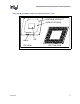
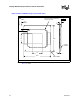
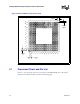
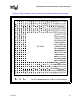
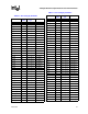
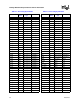
Package Mechanical Specifications and Pin Information
NOTE: Overall height as delivered. Values are based on design specifications and tolerances. This dimension
is subject to change based on OEM motherboard design or OEM SMT process.
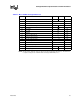
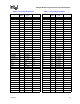
Table 4-2. Micro-FCBGA Package Dimensions
Symbol Parameter Min Max Unit
A Overall height, as delivered (Refer to Note 1) 2.60 2.85 mm
A2 Die height 0.82 mm
b Ball diameter 0.78 mm
D Package substrate length 34.9 35.1 mm
E Package substrate width 34.9 35.1 mm
D1 Die length 12.54 mm
E1 Die width 6.99 mm
e Ball Pitch 1.27 mm
K Package edge keep-out 5 mm
K1 Package corner keep-out 7 mm
K2 Die-side capacitor height – 0.7 mm
S Package edge to first ball center 1.625 mm
N Ball count 479 each
– Solder ball coplanarity 0.2 mm
Pdie Allowable pressure on the die for thermal solution – 689 kPa
W Package weight 4.5 g