
Intel Pentium M Processor on 90nm Process with 2-MB L2 Cache Datasheet


Datasheet 81
Thermal Specifications and Design Considerations
5.1.2 Thermal Diode Offset
A temperature offset value (specified as Toffset in Table 5-3) will be programmed into a
Pentium M Processor Model Specific Register (MSR). This offset is determined by using a thermal
diode ideality factor mean value of n = 1.0022 (shown in Table 5-3) as a reference. This offset must
be applied to the junction temperature read by the thermal diode. Any temperature adjustments due
to differences between the reference ideality value of 1.0022 and the default ideality values
programmed into the on-board thermal sensors, will have to be made before the above offset is
applied.
NOTES:
1. Intel does not support or recommend operation of the thermal diode under reverse bias. Intel does not
support or recommend operation of the thermal diode when the processor power supplies are not within their
specified tolerance range.
2. Characterized at 100 °C.
3. Not 100% tested. Specified by design/characterization.
4. The ideality factor, n, represents the deviation from ideal diode behavior as exemplified by the diode
equation:
I
FW
=I
s
*(e
(qVD/nkT)
-1)
Where I
S
= saturation current, q = electronic charge, V
D
= voltage across the diode, k = Boltzmann Constant,
and T = absolute temperature (Kelvin).
Value shown in the table is not the Pentium M Processor thermal diode ideality factor. It is a reference value
used to calculate the Pentium M Processor thermal diode temperature offset.
5. The series resistance, R
T
, is provided to allow for a more accurate measurement of the diode junction
temperature. R
T
as defined includes the pins of the processor but does not include any socket resistance or
board trace resistance between the socket and the external remote diode thermal sensor. R
T
can be used by
remote diode thermal sensors with automatic series resistance cancellation to calibrate out this error term.
Another application is that a temperature offset can be manually calculated and programmed into an offset
register in the remote diode thermal sensors as exemplified by the equation:
T
error
= [R
T
*(N-1)*I
FWmin
]/[(no/q)*ln N
6. Offset value is programmed in processor Model Specific Register.
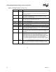
Table 5-2. Thermal Diode Interface
Signal Name Pin/Ball Number Signal Description
THERMDA B18 Thermal diode anode
THERMDC A18 Thermal diode cathode
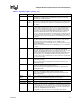
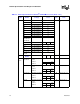
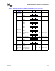
Table 5-3. Thermal Diode Specification
Symbol Parameter Min Typ Max Unit Notes
I
FW
Forward Bias Current 5 300 A Note 1
Toffset Thermal diode temperature
offset
-4 11 °C 2, 6
n Reference Diode Ideality
Factor used to calculate
temperature offset
1.0022 Notes 2, 3, 4
R
T
Series Resistance 3.06 Ohms 2, 3, 5