Intel® I/O Controller Hub 8 LAN NVM Map and Information Guide January 2008 316234-006 Revision 2.
INFORMATION IN THIS DOCUMENT IS PROVIDED IN CONNECTION WITH INTEL® PRODUCTS. NO LICENSE, EXPRESS OR IMPLIED, BY ESTOPPEL OR OTHERWISE, TO ANY INTELLECTUAL PROPERTY RIGHTS IS GRANTED BY THIS DOCUMENT.
NVM Information Guide—ICH8 Contents 1.0 Non-Volatile Memory (NVM) ...................................................................................... 5 1.1 Introduction ....................................................................................................... 5 1.2 NVM Programming Procedure Overview .................................................................. 5 1.3 EEUPDATE Utility................................................................................................. 7 1.3.
ICH8—NVM Information Guide 14 15 16 17 18 19 20 21 22 Extended Configuration Word 3 (Word 16h) ................................................................14 LED 1 Configuration and Power Management (Word 17h)...............................................15 LED Modes ..............................................................................................................16 LED 0 and 2 Configuration Defaults (Word 18h) ............................................................
ICH8—NVM Information Guide 1.0 Non-Volatile Memory (NVM) 1.1 Introduction The document is intended for designs using the 10/100/1000 Mb/s LAN controller that is integrated into the Intel® I/O Control Hub 8 (ICH8) device. The NVM space is used for hardware and software configuration. It is also read by software to determine and configure specific design features.
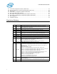
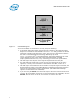
NVM Information Guide—ICH8 BIOS Region 1 ME Region 2 GbE Region 3 Flash Descriptor Region 0 Figure 1. LAN NVM Regions To access the NVM, it is essential to correctly setup the following: 1. A valid Flash Descriptor Region must be present. Details for the Flash Descriptor Region are contained in the ICH8 EDS. The FTOOL.exe utility provides the easiest method of configuring this descriptor region. This process is described in detail in the Intel® Active Management Technology OEM Bring-Up Guide. FTOOL.
ICH8—NVM Information Guide 6. The sector size of the NVM must equal 256 bytes, 4 KB, or 64 KB. When a Flash device that uses a 64 KB sector erase is used, the GbE region size must equal 128 KB. If the Flash part uses a 4 KB or 256-byte sector erase, then the GbE region size must be set to 8 KB. The NVM image contains both static and dynamic data. The static data is the basic platform configuration, and includes OEM specific configuration bits as well as the unique Printed Circuit Board Assembly (PBA).
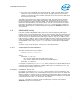
NVM Information Guide—ICH8 1.4 LAN NVM Format and Contents Table 1 lists the NVM maps for the LAN region. Each word listed is described in detail in the following sections. Table 1.
ICH8—NVM Information Guide LAN Word Offset NVM Byte Offset 1Bh to 2Fh 32h to 5Eh Reserved 30h to 3Eh 60h to 7Ch PXE Software Region PXE 3Fh 7Eh Software Checksum (bytes 00h through 7Dh) SW Notes: 1. 2. 3. 4. 1.4.1 HIgh Byte (Bits 15:8) Low Byte (Bits 7:0) Used By Image Value SW = Software: This is access from the network configuration tools and drivers. PXE = PXE Boot Agent: This is access from the PXE Option ROM code in BIOS.
NVM Information Guide—ICH8 1.4.3 Reserved (Word 04h) Table 4. Reserved (Word 04h) Bit 15:0 1.4.4 Table 5. Name Reserved Default FFFFh These bits are reserved and should be set to FFFFh. Image Version Information (Word 05h) Image Version Information (Word 05h) Bit 15 Name Reserved Default 0b Description This bit is reserved and should be set to 0b. 14:12 NVM Major Version -- This field represents the LAN NVM major version number.
ICH8—NVM Information Guide 1.4.8 PCI Initialization Control (Word 0Ah) This word contains initialization values that: • Set defaults for some internal registers. • Enable/disable specific features. • Determine which PCI configuration space values are loaded from the NVM. Table 8. PCI Initialization Control Word (Word 0Ah) Bit Default Description 15:13 Reserved 000b This field is reserved and should be set to 000b. 12 Reserved 1b This field is reserved and should be set to 1b.
NVM Information Guide—ICH8 1.4.11 Device ID (Word 0Dh) If the Load Vendor/Device IDs bit in word 0Ah is set to 1b, this word is read to initialize the Device ID of the LAN function. Device IDs for Intel® Platform LAN Connects Table 9. Device ID 1.4.
ICH8—NVM Information Guide 1.4.15 Shared Initialization Control (Word 13h) This word controls general initialization values. Table 11. Shared Initialization Control (Word 13h) Bit 15:14 Name SIGN Default 10b Description Valid Indication This is a 2-bit field indicating whether a valid NVM is present to the MAC. If this field does not equal 10b, the MAC does not read the NVM data and uses default values for device configuration. 00b = Invalid NVM. 01b = Invalid NVM. 10b = Valid NVM present.
NVM Information Guide—ICH8 1.4.16 Extended Configuration Word 1 (Word 14h) Table 12. Extended Configuration Word 1 (Word 14h) Bit 1.4.17 Table 13. 1.4.18 Table 14. Default Description 15 Reserved 0b Reserved. Must be set to 0b. 14 Reserved 1b 1b = ICH8 (B0/B1 stepping). 0b = ICH8 (A0 stepping). 13 Reserved 1b Set this field to 0b. 12 OEM Write Enable 1b OEM Write Enable 0b = Disable. 1b = Enable. Set this field to 0b.
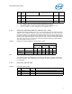
ICH8—NVM Information Guide 1.4.19 LED 1 Configuration and Power Management (Word 17h) This field specifies the default values for the LEDCTL register fields controlling the LED1 (LINK_1000) output behaviors and the OEM fields defining the PHY power management parameters loaded to the PHY_CTRL register. Table 15. LED 1 Configuration and Power Management (Word 17h) Bit Name Default Description 15 B2B Enable 1b This bit enables Smart Power Down in back-to-back link setup. 0b = B2B disabled.
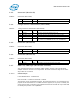
NVM Information Guide—ICH8 Table 16. 1.4.20 LED Modes Mode (Bits 3:0) Selected Mode Source Indication 0000b LINK_10/1000 Asserted when either 10 Mb/s or 1000 Mb/s link is established and maintained. 0001b LINK_100/1000 0010b LINK-UP Asserted when either 100 Mb/s or 1000 Mb/s link is established and maintained. Asserted when any speed link is established and maintained.
ICH8—NVM Information Guide Table 17. LED 0 and 2 Configuration Defaults (Word 18h) Bit Name Default Description 7 LED0 Blink 1b This bit indicates the initial value of the LED0_BLINK field. 0b = LED0 is non-blinking (recommended). 1b = LED0 is blinking. 6 LED0 Invert 0b This bit indicates the initial value of the LED0_IVRT field. 0b = LED0 has an active low output. 1b = LED0 has an active high output. This bit define the LED0 blink mode: 0b = Blink at 200 ms on and 200 ms off.
NVM Information Guide—ICH8 1.4.23 PXE Words (Words 30h - 3Eh) Words 30h through 3Eh (bytes 60h through 7Dh) have been reserved for configuration and version values to be used by PXE code. 1.4.23.1 Boot Agent Main Setup Options (Word 30h) The boot agent software configuration is controlled by the NVM with the main setup options stored in word 30h. These options are those that can be changed by using the Control-S setup menu or by using the IBA Intel Boot Agent utility.
ICH8—NVM Information Guide Bit Description Prompt Time. These bits control how long the "Press Control-S" setup prompt message appears, if enabled by DIM. 00b = 2 seconds (default) 01b = 3 seconds 10b = 5 seconds 11b = 0 seconds Note that the Ctrl-S message does not appear if 0 seconds prompt time is selected. 7:6 PT 5 Reserved Reserved 4:3 DBS Default Boot Selection. These bits select which device is the default boot device.
NVM Information Guide—ICH8 Table 19. Boot Agent Configuration Customization Options (Word 31h) Bit Description Signature. These bits must be set to 01b to indicate that this word has been programmed by the agent or other configuration software. 15:14 SIG 13:11 Reserved Reserved for future use. All bits must be set to 0b. 10:8 MODE Selects the agent's boot order setup mode.
ICH8—NVM Information Guide Bit 2 1 0 1.4.23.3 Name Description DPS Disable Protocol Select. If set to 1b, no changes to the boot protocol is allowed. The default for this bit is 0b; allow changes to the boot protocol. DTM Disable Title Message. If set to 1b, the title message displaying the version of the boot agent is suppressed; the Control-S message is also suppressed. This is for OEMs who do not want the boot agent to display any messages at system boot.
NVM Information Guide—ICH8 1.4.23.4 IBA Capabilities (Word 33h) Word 33h is used to enumerate the boot technologies that have been programmed into the Flash. It is updated by IBA configuration tools and is not updated or read by IBA. Table 21. IBA Capabilities Bit 1.4.24 Name Description Signature. These bits must be set to 01b to indicate that this word has been programmed by the agent or other configuration software. 15:14 SIG 13:5 Reserved Reserved for future use. All bits must be set to 0b.
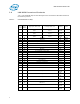
ICH8—NVM Information Guide Appendix A ICH8 NVM Contents and Sample Images This section contains a sample of raw NVM contents for the ICH8. All values for these images are hexadecimal. Table 22.
NVM Information Guide—ICH8 A.
ICH8—NVM Information Guide A.2 82566MM NVM Image with ICH8M Note: For use with ICH8 B-1 stepping only. Image has Intel® ACBS enabled.
NVM Information Guide—ICH8 A.
ICH8—NVM Information Guide A.
NVM Information Guide—ICH8 Note: 28 This page intentionally left blank.