
Datasheet

118 Datasheet
Intel
®
Celeron
®
Processor up to 1.10 GHz
The boxed Intel Celeron processors in the PPGA package at 500 MHz and below are shipped with
an unattached fan heatsink with two wire power-supply cables. These two wire fans do NOT
support the motherboard-mounted fan speed monitor feature. The Intel Celeron processor at
533 MHz and above ship with unattached fan heatsinks that have three power-supply cables. These
three wire fans DO support the motherboard-mounted fan speed monitor feature.
The power header on the baseboard must be positioned to allow the fan heatsink power cable to
reach it. The power header identification and location should be documented in the motherboard
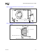
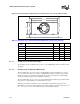
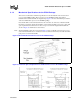
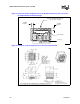
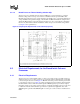
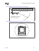
documentation or on the motherboard. Figure 43 shows the recommended location of the fan
power connector relative to the 242-contact slot connector. Figure 44 shows the recommended
location of the fan power connector relative to the 370-pin socket. For the S.E.P. Package, the
motherboard power header should be positioned within 4.75 inches (lateral) of the fan power
connector. The motherboard power header should be positioned within 4.00 inches (lateral) of the
fan power connector for the PPGA and FC-PGA/FC-PGA2 packages.
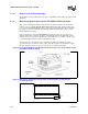
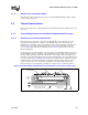
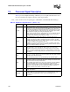
Figure 42. Boxed Processor Fan Heatsink Power Cable Connector Description
Table 58. Fan Heatsink Power and Signal Specifications
Description Min Typ Max
+12V: 12 volt fan power supply 10.2V 12V 13.8V
IC: Fan current draw 100 mA
SENSE: SENSE frequency (motherboard should pull this
pin up to appropriate Vcc with resistor)
2 pulses per
fan revolution
Pin Signal
Straight square pin, 3-pin terminal housing with
polarizing ribs and friction locking ramp.
0.100" pin pitch, 0.025" square pin width.
Waldom*/Molex* P/N 22-01-3037 or equivalent.
Match with straight pin, friction lock header on motherboard
Waldom/Molex P/N 22-23-2031, AMP* P/N 640456-3,
or equivalent.
1
2
3
GND
+12V
SENSE
123