
Datasheet

THERMAL SPECIFICATIONS
55
6. THERMAL SPECIFICATIONS AND DESIGN CONSIDERATIONS
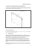
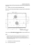
The processor contains a thermal plate for heatsink attachment. The thermal plate interface is intended to
provide for multiple types of thermal solutions. This chapter will provide the necessary data for a thermal
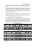
solution to be developed. See Figure 17 for thermal plate location.
Figure 17. Thermal Plate View
6.1 Thermal Specifications
This section provides power dissipation specifications for each version of the processor. The thermal plate
flatness is also specified for the S.E.C. cartridge.
6.1.1 POWER DISSIPATION
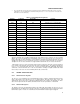
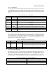
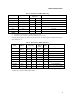
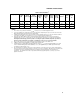
Table 47 and 48 provide the thermal design power dissipation for the processor. While the processor core
dissipates the majority of the thermal power, the system designer should also be aware of the thermal power
dissipated by the OCVR. Systems should design for the highest possible thermal power, even if a processor
with lower frequency is planned. The thermal plate is the attach location for all thermal solutions. The
maximum temperature for the entire thermal plate surface is shown in Table 47 and 48.
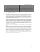
The processor power is dissipated through the thermal plate and other paths. The power dissipation is a
combination of power from the OCVR, the processor core (with integrated L2 cache), and the AGTL+ bus
termination resistors. The overall system thermal design must comprehend the Max Thermal power. The
combined power from the processor core, the second level cache, and the OCVR that dissipates through the
thermal plate is the Max Thermal power. The heatsink should be designed to dissipate the Max Thermal
power.
The thermal sensor feature of the processor cannot be used to measure T
PLATE
. The T
PLATE
specification
must be met regardless of the reading of the processor's thermal sensor in order to ensure adequate cooling
for the entire processor.