
Datasheet


BOXED PROCESSOR SPECIFICATIONS
86
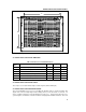
processor does not require additional heatsink supports. Heatsink supports are not shipped with the boxed
processor.
9.3 Thermal Specifications
This section describes the cooling requirements of the heatsink solution utilized by the boxed processor.
9.3.1 Boxed Processor Cooling Requirements
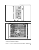
The boxed processor passive heatsink requires airflow horizontally across the heatsink to cool the processor.
The boxed processor heatsink will keep the processor thermal plate temperature, T
PLATE
, within the
specification, provided adequate airflow is directed into the system chassis, across the heatsink and out of the
system chassis. System integrators should perform thermal testing using thermocouples (see the section
entitled Processor Thermal Analysis) to evaluate the thermal efficiency of the system.
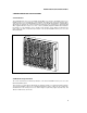
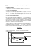
9.3.2 Boxed Processor Passive Heatsink Performance
The boxed processor’s passive heatsink is designed to provide effective heat transfer between the processor
package thermal plate and the air immediately surrounding the heatsink. The direction and temperature of air
flowing across the heatsink variably affects the efficiency of the heatsink. Figure 36 shows the thermal
efficiency of the boxed processor heatsink, using three different directions of airflow: horizontal, top-down, and
normal to the plane of the thermal plate. The performance characterization was completed in a wind tunnel,
using a processor running at maximum power and at maximum thermal specification. The characterization
assumes that air entering the heatsink is at constant temperature and uniformly traverses the heatsink, and
that heated air is evacuated from the chassis and is not re-circulated. The characterization also assumes
natural obstructions, such as the motherboard in a top-down airflow model.
To determine if a particular chassis has appropriate airflow to effectively cool the processor, measure the
“upstream” temperature (T
AMBIENT
, the ambient air temperature within the chassis) and the velocity of the air
entering the heatsink. The Y-axis in Figure 36 represents the thermal resistance (
PA
) and the X-axis
represents the airflow speed in linear feet per minute (lfm).
PA
can be calculated as the difference between
the thermal plate temperature and ambient air temperature (within the chassis) divided by the processor’s
maximum power specification.
θ
PA
=
T
PLATE
- T
AMBIENT
P
MAX
To determine if your airflow is adequate, determine the airflow speed and direction, and identify the
appropriate curve in Figure 36. Calculate
PA
and determine if it falls below the graphed line at the
appropriate airflow speed.
0.4
0.5
0.6
0.7
0.8
0.9
1
1.1
1.2
1.3
1.4
1.5
100 150 200 250 300 350 400
Airflow Speed (lfm)
PA
Horizontal
Normal
Top-Down
Aux. Fan (50mm)