
Datasheet


Intel® Xeon® Processor 3500 Series Datasheet Volume 1 83
Thermal Specifications
6.1.2 Thermal Metrology
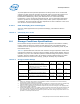
The minimum and maximum TTV case temperatures (T
CASE
) are specified in Ta b l e 6-1 ,
and Ta b l e 6- 2 and are measured at the geometric top center of the thermal test vehicle
integrated heat spreader (IHS). Figure 6-2 illustrates the location where T
CASE
temperature measurements should be made. For detailed guidelines on temperature
measurement methodology and attaching the thermocouple, refer to the appropriate
processor Thermal and Mechanical Design Guidelines (see Section 1.2).
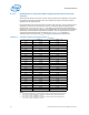
Notes:
1. Figure is not to scale and is for reference only.
2. B1: Max = 45.07 mm, Min = 44.93 mm.
3. B2: Max = 42.57 mm, Min = 42.43 mm.
4. C1: Max = 39.1 mm, Min = 38.9 mm.
5. C2: Max = 36.6 mm, Min = 36.4 mm.
6. C3: Max = 2.3 mm, Min = 2.2 mm
7. C4: Max = 2.3 mm, Min = 2.2 mm.
8. Refer to the appropriate Thermal and Mechanical Design Guide (see Section 1.2) for instructions on
thermocouple installation on the processor TTV package.
Figure 6-2. Thermal Test Vehicle (TTV) Case Temperature (T
CASE
) Measurement Location