
Datasheet


Interfaces
Intel
®
Xeon
®
Processor C5500/C3500 Series
Datasheet, Volume 1 February 2010
114 Order Number: 323103-001
2.5.5.1 NodeID Generation
This section contains an overview of how source address decoder generates the
NodeID. There are assumed fields for each decoder entry. In the case of some special
decoder ranges, the fields in the decoder may be fixed or shifted to match different
address ranges, but the basic flow is similar across all ranges.
Table 64 defines the fields used per memory source address decoder. The process for
using these fields to generate a NodeID is:
1. Match Range
2. Select TargetID from TargetID List using the Interleave Select address bit(s)
3. NodeID[5:0] is directly assigned from the TargetID
2.5.5.2 Memory Decoder
A single Decoder entry defines a contiguous memory range. Low order address
interleaving is provided to distribute this range across up to two home agents. All
ranges must be non-overlapping and aligned to 64 MB.
A miss of the SAD results in an error. Outbound snoops are dropped. Inbound requests
return an unsupported request response. Protection of address ranges from inbound
requests is done in range decoding prior to the SAD or can be done using holes in the
SAD memory mapping if the range is aligned to 64 MB.
Note: The memory source address decoder in IIO contains no attribute, unlike the processor
SAD. All attribute decode (MMIO, memory, Non-Coherent memory) is done with coarse
range decoding prior to the request reaching the Source Address Decoder. See
Chapter 6.0, “System Address Map” for details on the coarse address decode ranges.
2.5.5.3 I/O Decoder
The MMIOL and MMIOH regions use standard memory decoders. The I/O decoder
contains a number of special regions as shown below.
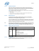
Table 64. Memory Address Decoder Fields
Field Name
Number of
Bits
Description
Valid 1 Enables the source address decoder entry
Interleave
Select
3
Determines how targets are interleaved across the range. Sys_Interleave
value is set globally using the QPIPINT: Intel
®
QPI Protocol Mask register.
Modes:
0x0 - Addr[8:6]
0x1 - Addr[8:7] & Sys_Interleave
0x2 - Addr[9:8] & Sys_Interleave
0x3 - Addr[8:6] XOR Addr[18:16]
0x4 - Addr[8:7] XOR Addr[18:17] & Sys_Interleave
>0x4 - Reserved
TargetID List 48 A list of eight 6-bit TargetID values. Only two Home Node IDs are supported.