
Datasheet


Intel
®
Xeon
®
Processor C5500/C3500 Series
February 2010 Datasheet, Volume 1
Order Number: 323103-001 147
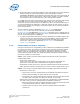
PCI Express Non-Transparent Bridge
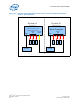
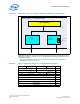
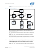
Figure 53 describes the three usage models and their behavior regarding crosslink
training.
The following acronyms need to be understood to decode the crosslink figure shown
above. Upstream device (USD)/Downstream port (DSP) and Downstream device
(DSD)/Upstream port (USP).
This assumes both devices have been powered on and are capable of sending training
sequences.
Case 1: Intel
®
Xeon
®
processor C5500/C3500 series Root Port (RP) connected to
external endpoint (EP)
No Crosslink configuration required: Hardware will automatically strap the port as an
USD/DSP when the PPD register, Port Definition field, is set to “00”b (RP).
The RP will train as USD/DSP and the EP will train as DSD/USP. No conflict occurs and
link training proceeds without need for crosslink training.
Note: When configured as a RP. the PE_NTBXL pin should be left as a no-connect
(NTB logic does not look at the state of the PE_NTBXL pin when configured as
a RP). The PPD Crosslink Control Override field bits 3:2 have no meaning
when configured as a RP.
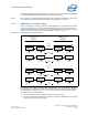
Case 2: Intel
®
Xeon
®
processor C5500/C3500 series NTB connected to external RP
Figure 53. Crosslink Configuration
NTB
NTB
RP
EP
Root Port
(RP)
Root
Complex
Case 1
Case 2
Case 3
DSP
USP
USP
DSP
Type:
Root Port
Type:
NTB/RC
Type:
NTB/NTB
Root
Complex
(RC)
USD
DSD
USD
DSD
USD
DSD
DSP
USP
Root
Complex
NTBCROSSLINK
NTB
NTBCROSSLINK
DSD
NC
NTBCROSSLINK
NC
NTBCROSSLINK
NC