
Datasheet

Intel
®
Xeon
®
Processor C5500/C3500 Series
February 2010 Datasheet, Volume 1
Order Number: 323103-001 391
Reliability, Availability, Serviceability (RAS)
11.3.3.7 Error Counters
This feature allows the system management controller to monitor the component’s health by
periodically reporting the correctable error count. The error RAS structure already provides a first
error status and a second error status. Because the response time of system management is on the
order of milliseconds it is not possible to read and clear the error logs in time to detect short bursts of
errors across the chip. Over a long time period, the software uses these values to monitor the rate of
change in error occurrences. This can help to identify potential component degradations, especially
with respect to the memory interface.
11.3.3.7.1 Feature Requirements
A register with one-hot encoding will select which error types participate in error counting. It is
unlikely that more than one error will occur within a cluster at a given time. Therefore, it is not
necessary to count more than one occurrence in one clock cycle. The selection register will OR
together the selected error types to form a single count enable. This means that only one increment
of the counter will occur for one or all types selected. Register attributes are set to write 1 to clear.
Each cluster has one set of error counter/control registers.
•The Intel
®
QuickPath Interconnect port will contain one 7-bit counter (ERRCNT[6:0]).
— Bit[7] is an overflow bit; all bits are sticky with a write logic 1 to clear.
• The IIO cluster (core) contains one 7-bit counter (ERRCNT[6:0]).
— Bit[7] is an overflow bit; all bits are sticky with a write logic 1 to clear.
• Each x4 PCI Express port contains one 7-bit counter (ERRCNT[6:0]) with a correctable error
status selection register.
— Bit[7] is an overflow bit; all bits are sticky with a write logic 1 to clear.
• The DMI port contains one 7-bit counter (ERRCNT[6:0]) with a correctable error status selection
register.
— Bit[7] is an overflow bit; all bits are sticky with a write logic 1 to clear.
11.3.3.8 Stop on Error
The System Event Map register selects the severity levels that activate Stop on Error (error freeze). A
reset is required to clear the event, or a configuration write (using SMBus) to the stop on error bit in
the selection register. Continued operation after an error freeze is not guaranteed. See the System
Event Map register (SYSMAP).
11.4 IIO Intel
®
QuickPath Interconnect Interface RAS
The following sections provide an overview of the IIO Intel
®
QuickPath Interconnect RAS features. IIO
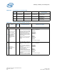
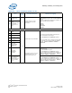
CSI RAS features are summarized as shown in Table 127
Table 127. IIO Intel
®
QPI RAS Feature Support
Feature
IIO Intel
®
QPI 0
(Internal Between CPU and IIO)
Intel
®
QPI 1
(External)
Link Level 8-bit CRC No Yes
Link Level Retry No Yes
Dynamic Link Retraining and Recovery No (x20 link width only) No (x20 only)
Detection, logging and Reporting
Yes
(Only for Protocol and Routing Support)
No