
Datasheet


Intel® S5000 Server Board Family Datasheet System BIOS
Revision 1.3
Intel order number D38960-006
47
The LEDs are controlled by the BMC, but the BIOS informs the BMC of the memory errors that
are described in the table. The methods used to inform the BMC of the error(s) are described
section 3.3.10.2.1. It is the responsibility of the BMC to modify the LED behavior according to
the notification received from the BIOS.
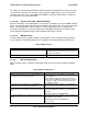
3.3.10.2.4.1 System Status LED – BMC Initialization
When the AC power is first applied to the system and 5 V standby is present, the BMC controller
on the server board requires 15-20 seconds to initialize. During this time, the system status LED
blinks, alternating between amber and green, and the power button on the control panel is
disabled, preventing the server from powering up. After BMC initialization has completed, the
status LED will stop blinking and the power button functionality is restored.
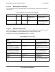
3.3.10.2.5 NMI Generation
The BIOS will generate an NMI to halt the system progress when normal memory operations
cannot continue. The following table lists the conditions under which NMI generation occurs.
Table 8. NMI Generation
Error Event Mode of Operation
Uncorrectable error occurs at runtime. Non-RAS (single channel or maximum performance)
or sparing mode or mirroring mode when the primary
and mirror are both bad.
Fatal FBD errors occur at runtime. All modes.
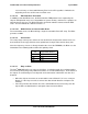
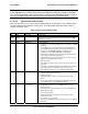
3.3.10.3 Mirroring Mode Errors
When mirroring mode is enabled, the BIOS will report errors in accordance with the following
table:
Table 9. Mirroring Mode Errors
Event Actions
Mirroring mode selected by the user, but the BIOS failed
to configure the system in mirroring mode.
Error message in the error manager at end of POST.
Error ID 0x85FD
Current Memory Configuration field in the Advanced |
Memory tab in the BIOS Setup utility indicates maximum
performance or single-channel mode, depending upon
the FBDIMM population
Correctable error in the primary or secondary branch.
Number of errors is less than the threshold of 10
SEL generated with Sensor Offset = Correctable Error.
Correctable error in primary or seconday branch, number
of such errors in the same branch reaches the threshold
of 10.
SEL generated with Sensor Offset = Correctable Error
SEL generated with Sensor Offset = Correctable Error
Threshold
DIMM fault LED for the failed DIMM lights.
First uncorrectable ECC error in primary and secondary
branch
SEL generated with Sensor Offset = Uncorrectable Error.
Failed memory is taken off-line.
DIMM fault LED for the failed FBDIMM is lit.
NMI is asserted.