
Datasheet

Intel® Light Guided Diagnostics Intel® Server Board S1400SP TPS
Revision 1.0
Intel order number G64248-001
96
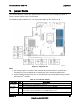
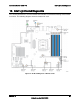
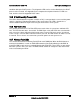
Figure 28. Memory Slot Fault LED Locations
10.1
System ID LED
The server board includes a blue system ID LED which is used to visually identify a specific
server installed among many other similar servers. There are two options available for
illuminating the System ID LED:
1. The front panel ID LED Button is pushed, which causes the LED to illuminate to a solid
on state until the button is pushed again.
2. An IPMI Chassis Identify command is remotely entered, which causes the LED to blink.
The System ID LED on the server board is tied directly to the System ID LED on system front
panel if present.
10.2
System Status LED
The server board includes a bi-color System Status LED. The System Status LED on the server
board is tied directly to the System Status LED on the front panel (if present). This LED
indicates the current health of the server. Possible LED states include solid green, blinking
green, blinking amber, and solid amber.
When the server is powered down (transitions to the DC-off state or S5), the BMC is still on
standby power and retains the sensor and front panel status LED state established before the
power-down event.
When AC power is first applied to the system, the status LED turns solid amber and then
immediately changes to blinking green to indicate that the BMC is booting. If the BMC boot
process completes with no errors, the status LED will change to solid green.