
Datasheet

Intel® Server Board S1400SP TPS
Intel® Light Guided Diagnostics
Revision 1.0
Intel order number G64248-001
99
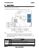
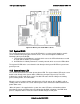
condition during the POST process. The diagnostic LEDs can be used to identify the last POST
process to be executed. See Appendix D for a complete description of how these LEDs are
read, and for a list of all supported POST codes.
10.5
5 Volt Stand-By Present LED
This LED is illuminated when a power cord (AC or DC) is connected to the server and the power
supply is supplying 5 Volt Stand-by power to the server board. This LED is intended as a
service caution indicator to anyone accessing the inside of the server system.
10.6
Fan Fault LEDs
The server board includes a Fan Fault LED next to each of the six system fans and both CPU
fans. The LED has two states: On and Off. The BMC lights a fan fault LED if the associated fan-
tach sensor has a lower critical threshold event status asserted. Fan-tach sensors are manual
re-arm sensors. Once the lower critical threshold is crossed, the LED remains lit until the sensor
is rearmed. These sensors are rearmed at system DC power-on and system reset.
10.7
Memory Fault LEDs
The server board includes a Memory Fault LED for each DIMM slot. When the BIOS detects a
memory fault condition, it sends an IPMI OEM command (Set Fault Indication) to the BMC to
instruct the BMC to turn on the associated Memory Slot Fault LED. These LEDs are only active
when the system is in the ‘on’ state. The BMC will not activate or change the state of the LEDs
unless instructed by the BIOS.