
Datasheet


Intel® Server Board S1400SP TPS Appendix C: POST Code Diagnostic LED Decoder
Revision 1.0
Intel order number G64248-001
133
Appendix C: POST Code Diagnostic LED Decoder
As an aid to assist in trouble shooting a system hang that occurs during a system’s Power-On
Self Test (POST) process, the server board includes a bank of eight POST Code Diagnostic
LEDs on the back edge of the server board.
During the system boot process, Memory Reference Code (MRC) and System BIOS execute a
number of memory initialization and platform configuration processes, each of which is assigned
a specific hex POST code number. As each routine is started, the given POST code number is
displayed to the POST Code Diagnostic LEDs on the back edge of the server board.
During a POST system hang, the displayed post code can be used to identify the last POST
routine that was run prior to the error occurring, helping to isolate the possible cause of the hang
condition.
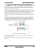
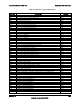
Each POST code is represented by eight LEDs; four Green and four Amber. The POST codes
are divided into two nibbles, an upper nibble and a lower nibble. The upper nibble bits are
represented by Amber Diagnostic LEDs #4, #5, #6, #7. The lower nibble bits are represented by
Green Diagnostics LEDs #0, #1, #2 and #3. If the bit is set in the upper and lower nibbles, the
corresponding LED is lit. If the bit is clear, the corresponding LED is off.
Figure 32. POST Code Diagnostic LED Layout
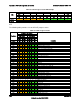
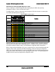
In the following example, the BIOS sends a value of ACh to the diagnostic LED decoder. The
LEDs are decoded as follows:
Note: Diag LEDs are best read and decoded when viewing the LEDs from the back of the
system.